Hardware Connection
Item List
| Item | Quantity | Notes |
|---|---|---|
| VR Equipment | 1 | Includes VR headset, left and right controllers, adapters, power cables |
| TeleSuit (Upper Body Mocap/Full Body Mocap, Includes Main Control) | 1 | Upper Body Mocap/Full Body Mocap |
| TeleBox (Includes 1T SSD Storage) | 1 | |
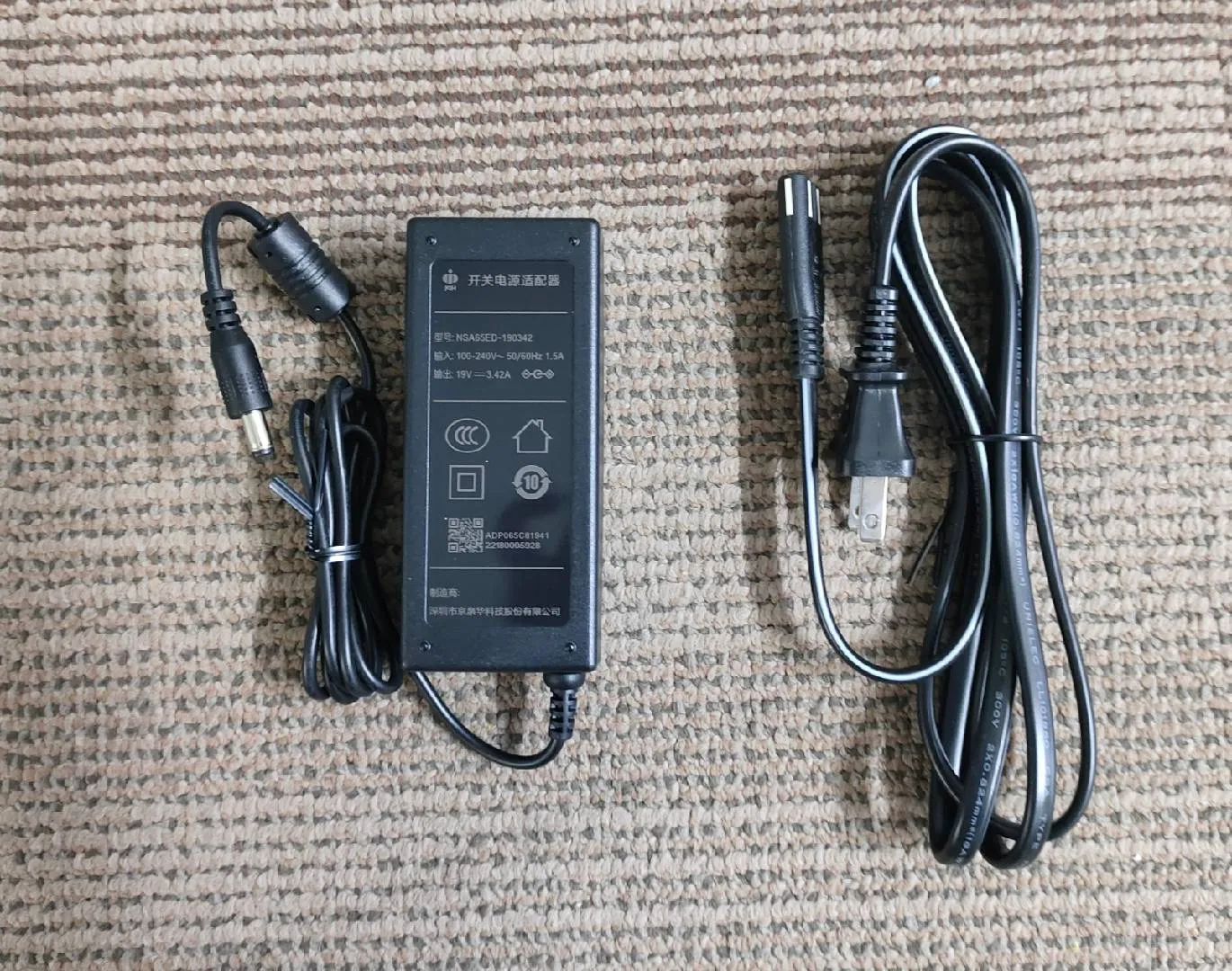
| 19V Power Adapter (TeleSuit Main Control Power Supply) | 1 | Will be replaced with battery for continuous power supply in the future |
| 5V Power Adapter (TeleBox Power Supply) | 1 | |
| Dual-Type-C Data Cable (2 meters) | 1 | Used to extend the VR headset's power cable |
| Ethernet Cable (2 meters) | 1 | |
| Straps | 5/11 | Straps (30cm×4, 80cm×1) / Straps (30cm×6, 60cm×4, 80cm×1) |
1. Wearing the TeleSuit
Take out the TeleSuit from the packaging box and put it on:
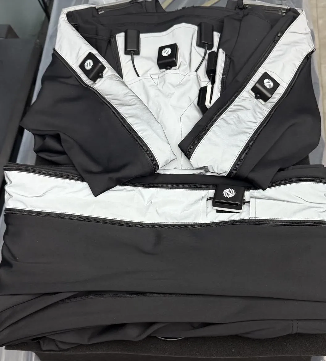
1.1 Wearing Effect
 Upper body wearing effect
 Full body wearing effect
If the TeleSuit size is too large, use straps to secure the full-body sensors, ensuring they fit snugly against the torso.
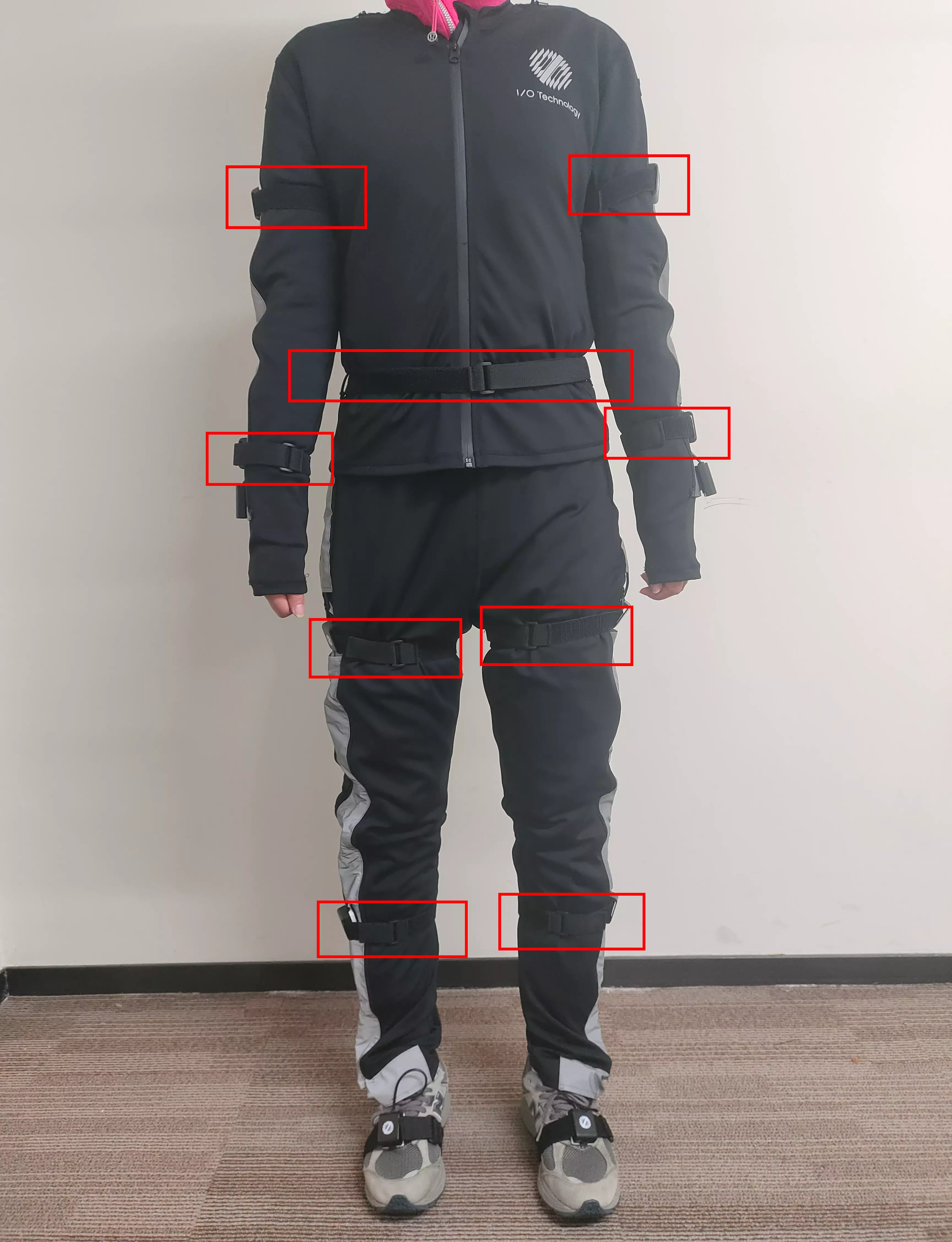 Illustration of securing with straps for the full body
2. TeleSuit Waist Aviation Connector Guide
(If you purchased the version without lower limbs, you can skip this section)
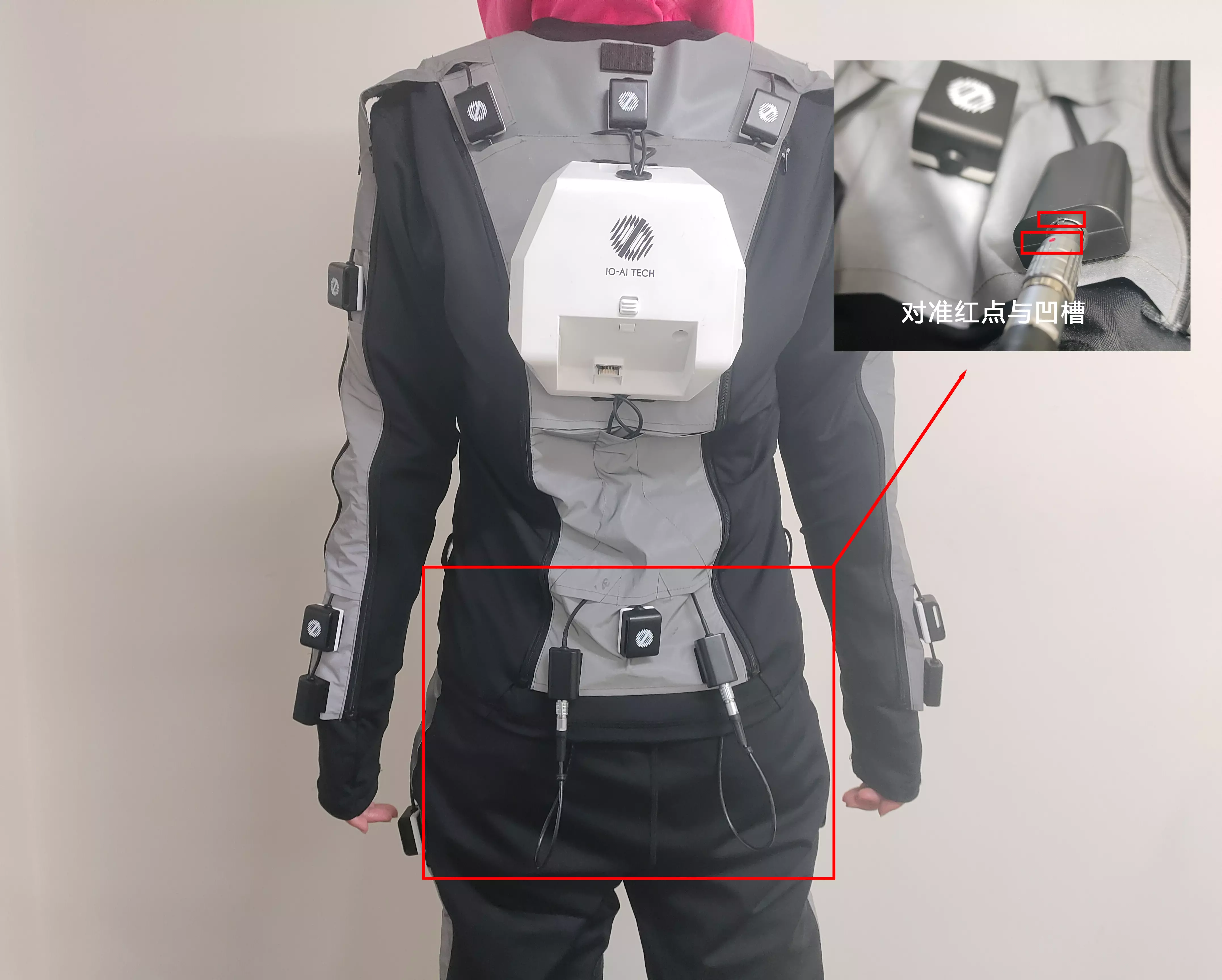
After wearing the motion capture suit, another person is required to assist with connecting the aviation connectors at the waist. Connection steps:
2.1 Left Side Connection
Locate the left hip aviation connector on the pants and the left waist aviation socket on the top.
Align the red dot on the connector with the groove on the socket, ensure the direction is correct, then firmly insert until fully connected.
After connecting, gently pull the connector to confirm it is secure with no looseness.
2.2 Right Side Connection
Follow the same procedure as the left side to connect the right hip aviation connector on the pants with the right waist aviation socket on the top.
2.3 Inspection and Confirmation
After connecting both sides, check each connector to ensure they are fully inserted, ensuring a stable connection with no looseness or errors.
2.4 ⚠️ Important Notes
You must align the red dot on the connector with the groove on the socket before inserting, to avoid damaging the interface due to incorrect orientation.
It is recommended that the wearer maintains a standing posture to facilitate the connector to be securely attached by the operator.
3. TeleSuit Main Control Power Supply Guide
The TeleSuit main control unit at the back of the suit requires power. Power adapter information:
The compatible power adapter specifications are 19V, with a "TeleSuit Main Control Power Supply" label on the adapter.
3.1 Connection Steps
Connect one end of the dual-round connector data cable to the adapter.
Locate the round connector slot on the back of the TeleSuit main control unit, and insert the connector firmly until it is in place.
Plug the other end of the adapter into a standard power outlet and ensure the power is turned on.
3.2 ⚠️ Important Notes
Do not use adapters other than 19V, as it may damage the device or affect power supply stability.
When inserting the power adapter, ensure the connection is secure with no looseness.
During use, avoid pulling or pressing the power cable to maintain power supply safety.


3.3 TeleSuit Main Control Indicator Lights Explanation
The three indicator lights at the bottom right of the TeleSuit main control are used to display the operating status of different modules of the main control. After powering on, you can quickly determine if the main control is functioning normally based on their status.
| Indicator Light | Function | Normal Blinking State |
|---|---|---|
| Top Indicator Light | Motion Capture Development Board Status | Green Light blinking |
| Middle Indicator Light | Main Control Status | Green Light steady on |
| Bottom Indicator Light | Router Status | Red Light steady on |
When the TeleSuit router is powered on, the bottom indicator light is green. After waiting 1-2 minutes for startup to complete, it changes to red.
3.4 ⚠️ Fault Diagnosis and Handling
If the middle indicator light - Main Control Status Light is red, unplug the power adapter from the main control's round connector end and reconnect it, until the middle indicator light changes to a steady green state.

4. TeleBox Power Connection
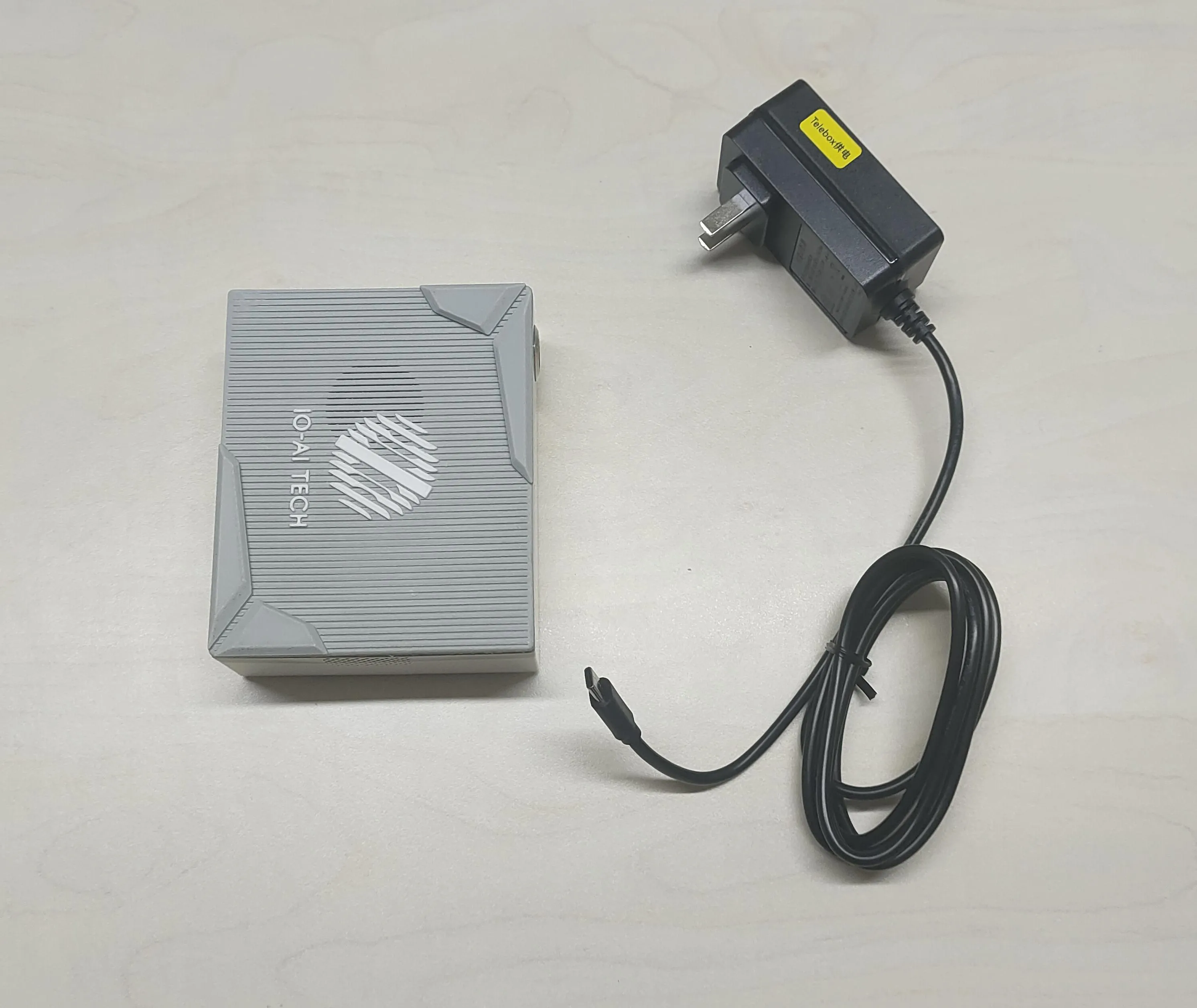
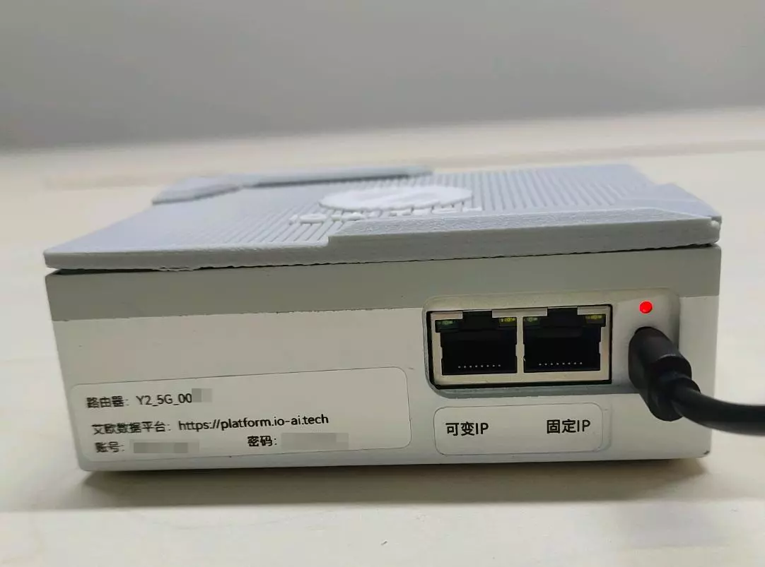
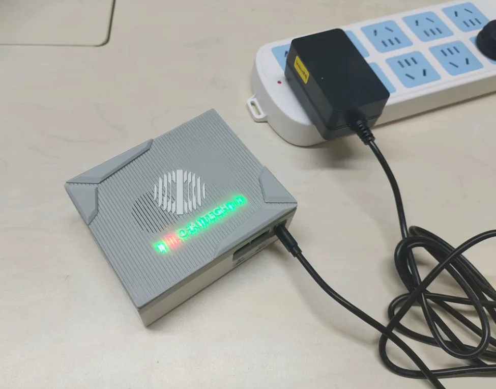
Insert the adapter labeled "TeleBox Power Supply" into the Type-C port on the side of the TeleBox, and the other end into a power outlet. At this point, the indicator light above the Type-C port will first turn red, then change to purple after 5 seconds, and finally to a red-blue flashing state after another 5 seconds.
4.1 TeleBox Power Connection Steps
Locate the power adapter labeled "TeleBox Power Supply".

Insert one end of the adapter (Type-C plug) into the Type-C port on the side of the TeleBox.
Insert the other end of the adapter into a power outlet, ensuring the power supply is normal.
4.2 Power Indicator Light Status
Initial Status: After connecting power, the indicator light above the Type-C port changes in the following sequence:
Red (Power On) ------ Power has been initiated.
Purple (After 5 seconds) ------ System is initializing.
Red-Blue Flashing (After another 5 seconds) ------ TeleBox is powered normally and ready.
4.3 TeleBox Operating Status Indicator Lights Explanation
Indicator Light Location
A row of status indicator lights is configured on top of the TeleBox outer box (at IO-AI TECH), used to display the device's operating status.
Operating Status Explanation
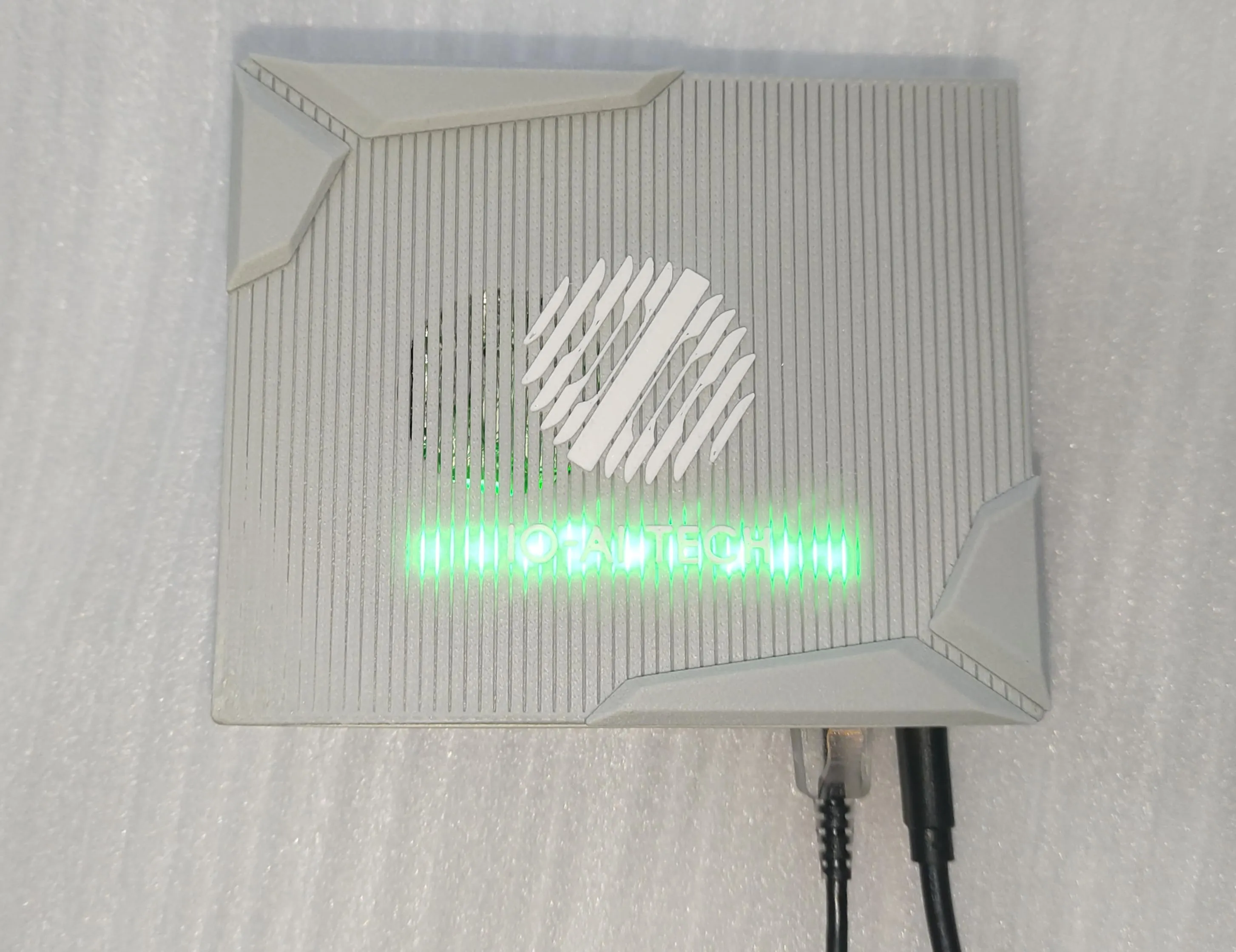
After powering on, wait approximately 1 minute. The status indicator lights will light up (at IO-AI TECH), with the second light from the left being red and the remaining lights green. (When entering teleoperation mode, all lights will turn green).
5. Main Control and TeleBox Connection Guide
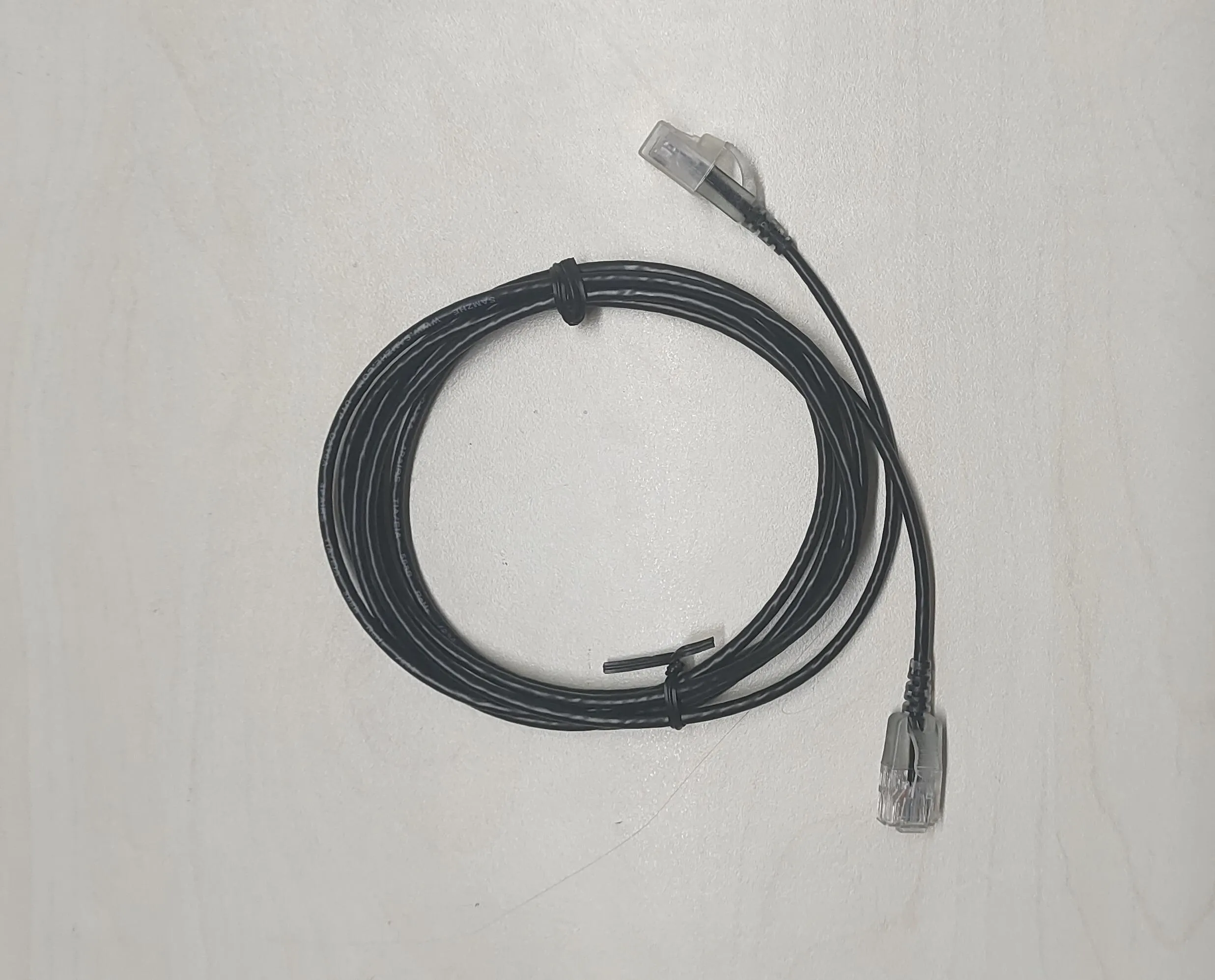
5.1 Prepare an Ethernet Cable
Take out the compatible Ethernet cable and check both ends for any damage.
5.2 Connect the Ethernet Cable

Insert one end of the Ethernet cable into the rectangular groove interface above the main control, ensuring a secure connection.
Insert the other end of the Ethernet cable into the "Fixed IP" port on the TeleBox, where the indicator light should flash orange, indicating a successful connection.

5.3 Observe the Status
After connection, observe the indicator lights above the TeleBox:
All light beads turn green, indicating the device has successfully entered teleoperation collection mode.
6. Wearing the VR Equipment
6.1 VR Equipment Components Confirmation
Includes the following main components:
Headset: Displays images, the core interactive device.
Left and Right Controllers: Facilitate operations and interactions in the virtual world.
Adapters: Original chargers compatible with the power cables.
White Power Cable: Used for charging the headset, of moderate length, suitable for general use scenarios.
Dual-Type-C Data Cable (2 meters): Provides a longer connection distance, suitable for complex scenarios or when power outlet positions are far apart.

VR Headset Startup and Battery Status Confirmation
Locate the Power Button
The power button is located on the left side of the VR headset device.
6.2 Starting the Device
Press and hold the power button for 3 seconds, then release.
Observe the status of the device's power indicator light.

Determine Battery Status
White Steady Light: Sufficient battery, can be used normally.
Orange Steady Light: Low battery, needs charging.
Charging Operation
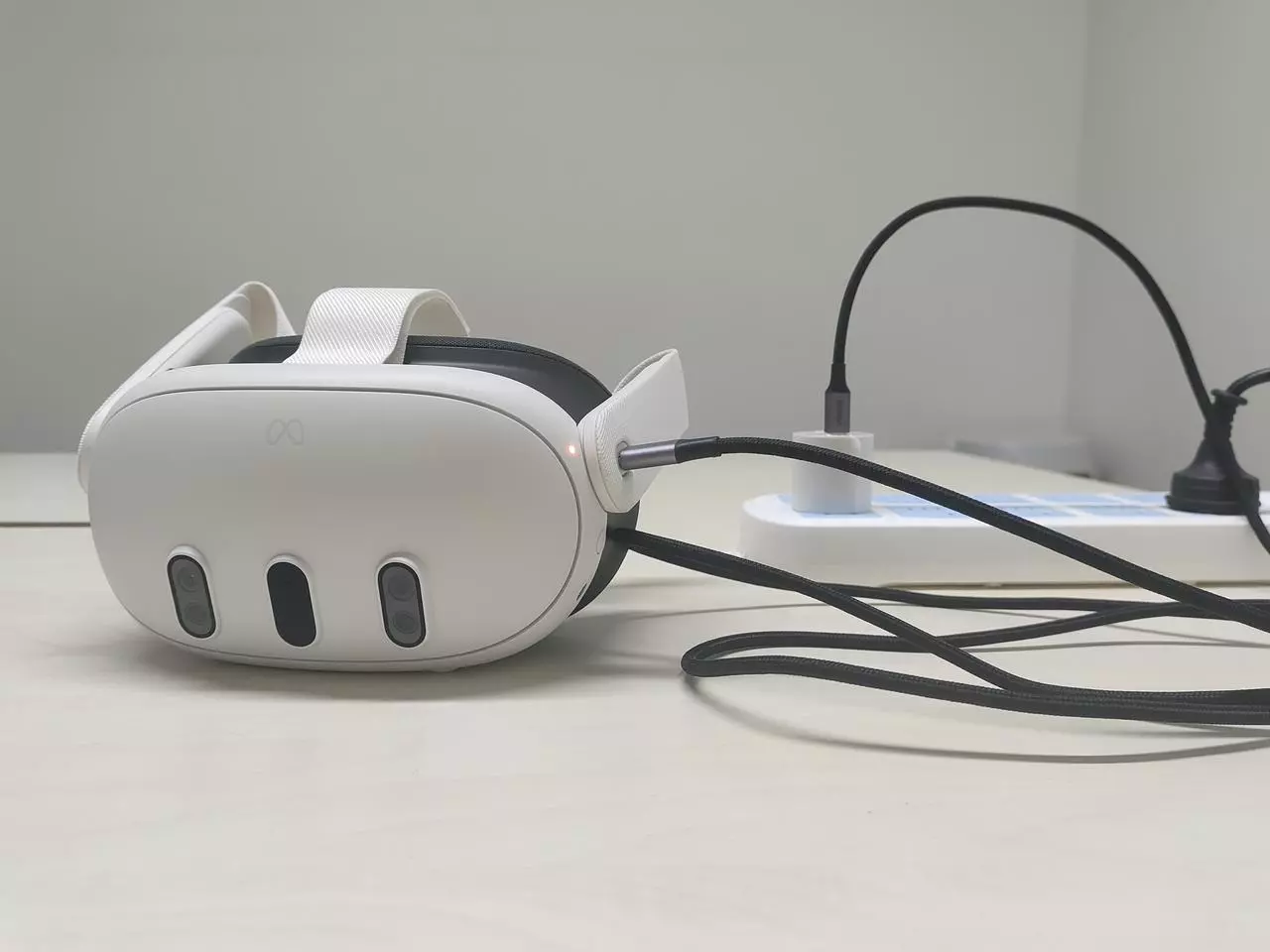
Insert one end of the data cable into the charging port on the left side of the VR headset, ensuring the connection is secure.
Insert the other end of the data cable into the Quest original adapter.
Plug the adapter into a power outlet, ensuring the power supply is normal.
After powering on, the VR headset enters charging mode, which can be confirmed through the indicator light. When the power indicator light is orange, it indicates charging is in progress; when the power indicator light is green, it indicates the battery is fully charged.
6.3 Controller Pairing Operation and Battery Status Confirmation
Start the VR headset and wear the VR headset.
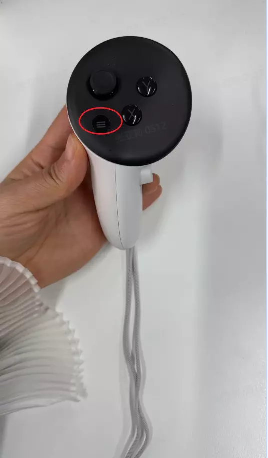
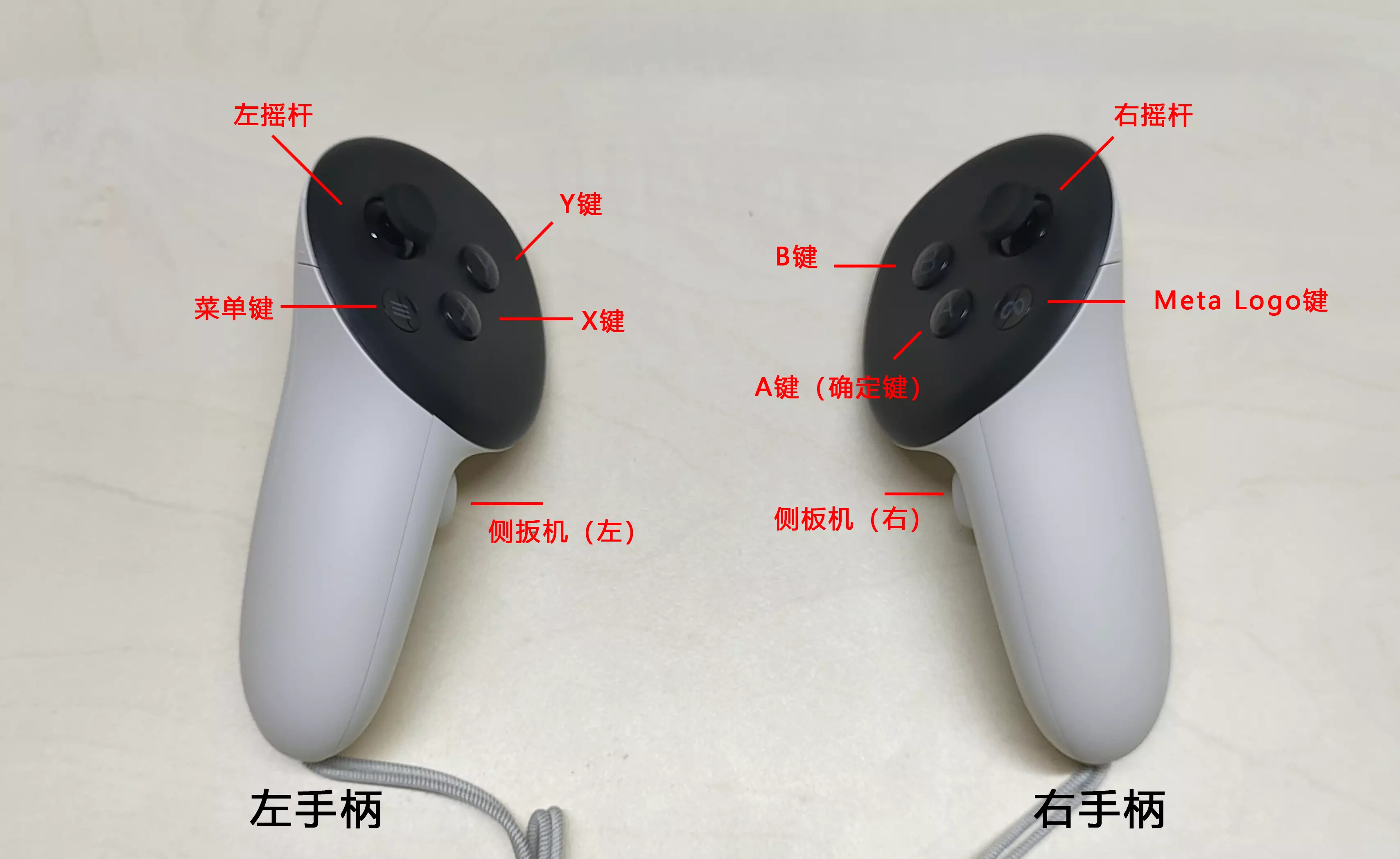
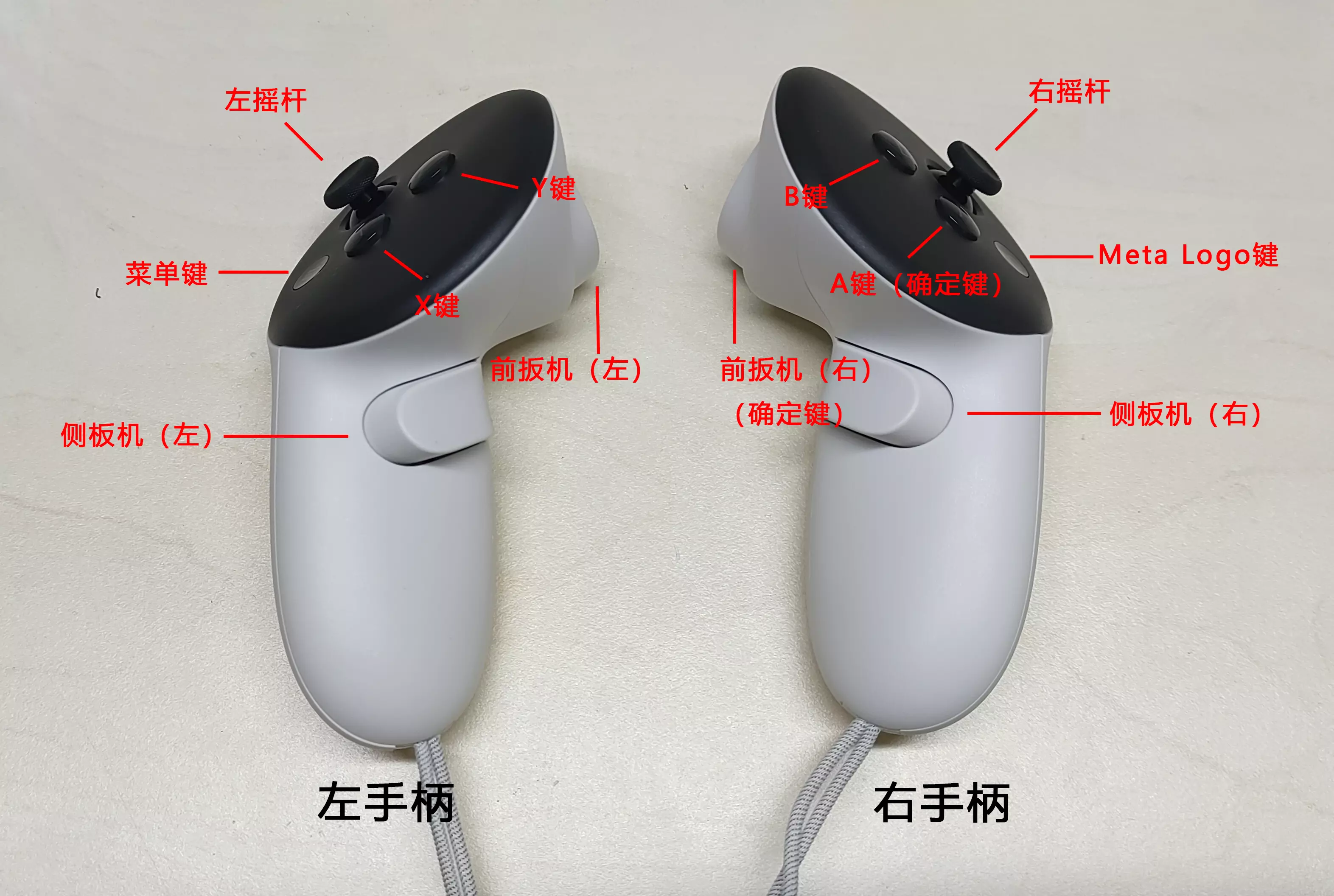
Locate the "Menu button" on the left controller and the "MetaLogo button" on the right controller (specific locations are shown in the images below).
Press and hold both buttons simultaneously for about 2 seconds to pair, until you feel haptic feedback (vibration).
| Left Controller | Right Controller |
|---|---|
 |  |
7. After Connecting the VR
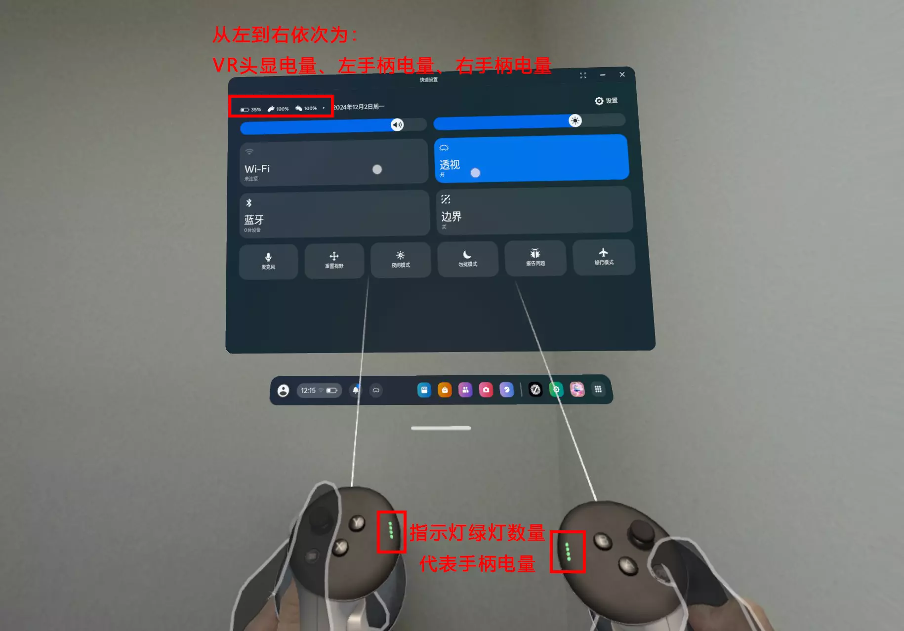
After successful pairing, the battery status of the headset and both controllers can be seen in the VR headset.
7.1 Turn On the VR Headset Volume
Locate the Volume Button on the right side at the bottom of the VR headset device.
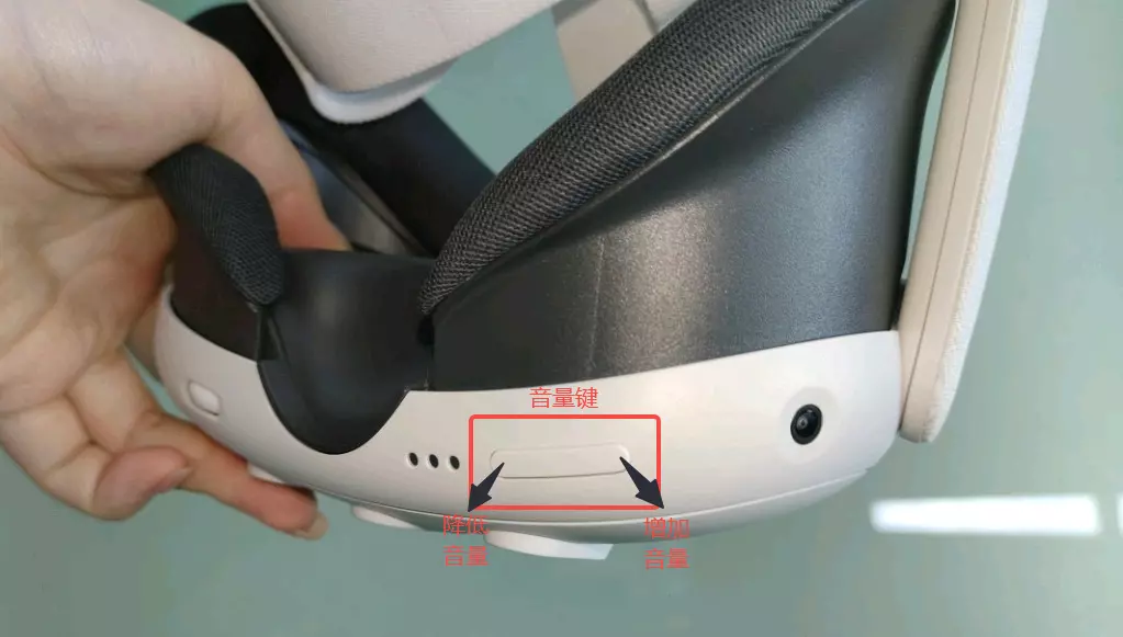
Adjust the volume to an appropriate level: Press the left or right half of the volume button to adjust the volume to a suitable level, ensuring you can receive audio alerts during the debugging process.
7.2 Controller Button Function Introduction
Press both joysticks simultaneously to enter transparency mode.
Right Joystick: Scroll through pages.
Press and hold the A button and drag up/down: Scroll through pages.
Single-click the A button / Press the front trigger on the right controller: Confirm.
 |  |
|---|---|
| Front of the Controller | Side of the Controller |
8. Completion
Hardware is ready. Let's proceed to software usage.