Hardware Connection
Watch Videos to Quickly Learn Wearing Steps
Select Product Configuration to View Wearing Video
Click to expand aviation plug usage
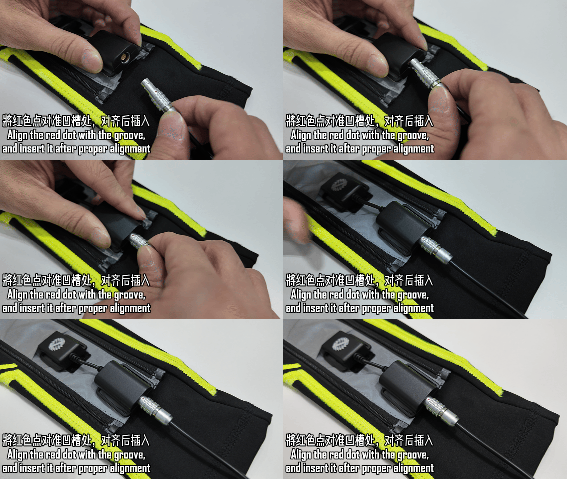
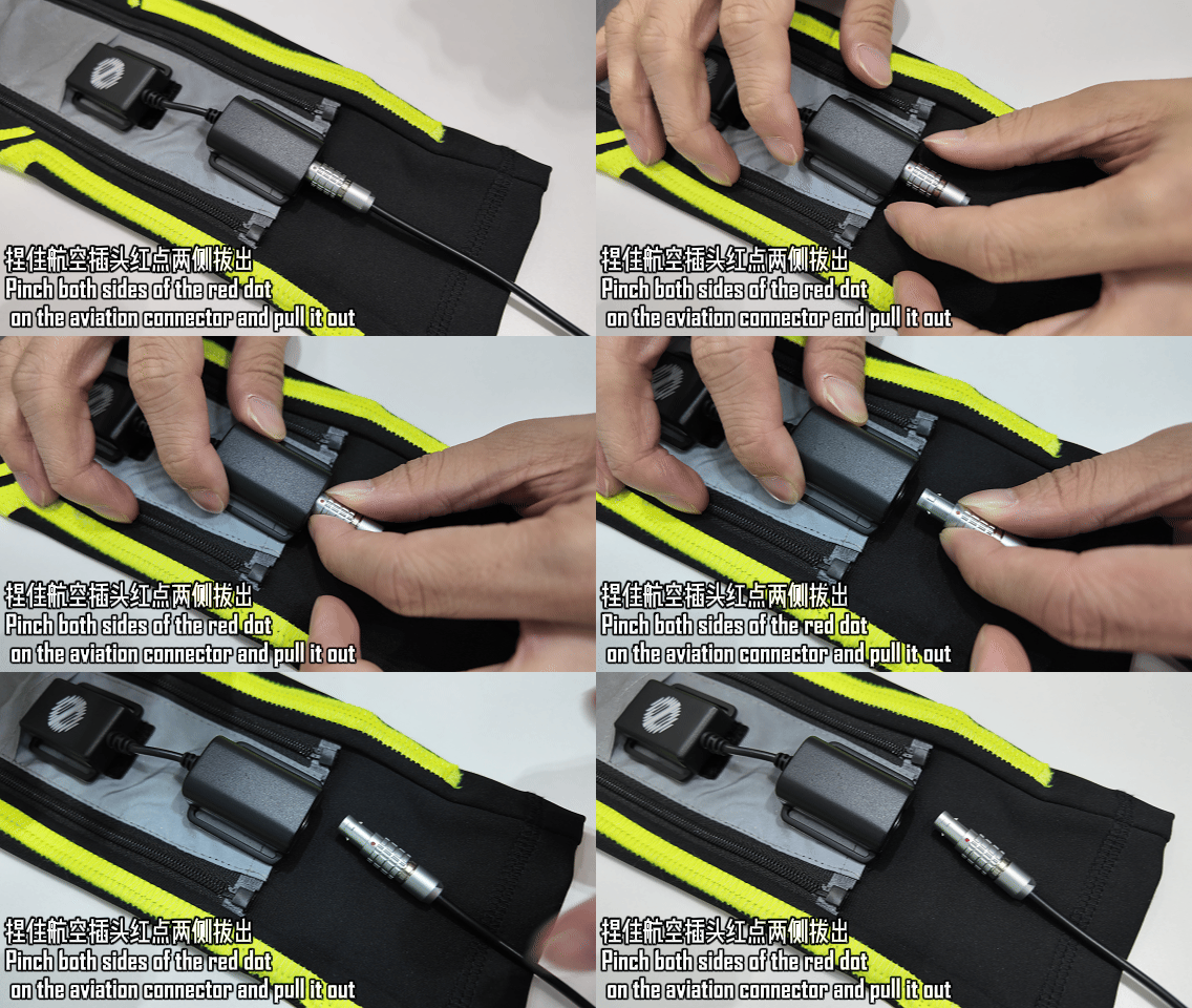
All parts of the motion capture suit connect to the main controller through aviation plugs. Note the following when plugging and unplugging:
- Insert: Align the red dot on the plug with the groove on the socket, push it in fully, then gently wiggle the plug to confirm a secure connection.
- Remove: Pinch both sides of the plug and pull it straight out; do not pull on the cable.
Start TeleSuit Main Control
Power Connection
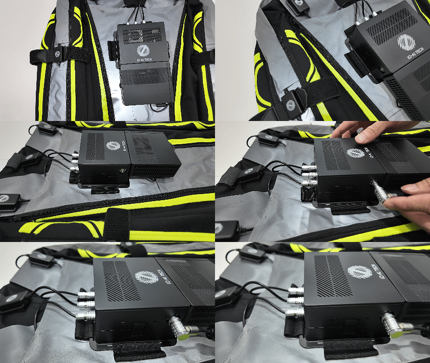
Connect and power on using the factory-supplied charger.
Main Control Indicator and Mocap Indicator
After successful startup, the main control indicator will show slow blinking, and the Mocap indicator will remain solid green (after starting motion capture, the Mocap indicator will switch to blue-green blinking).

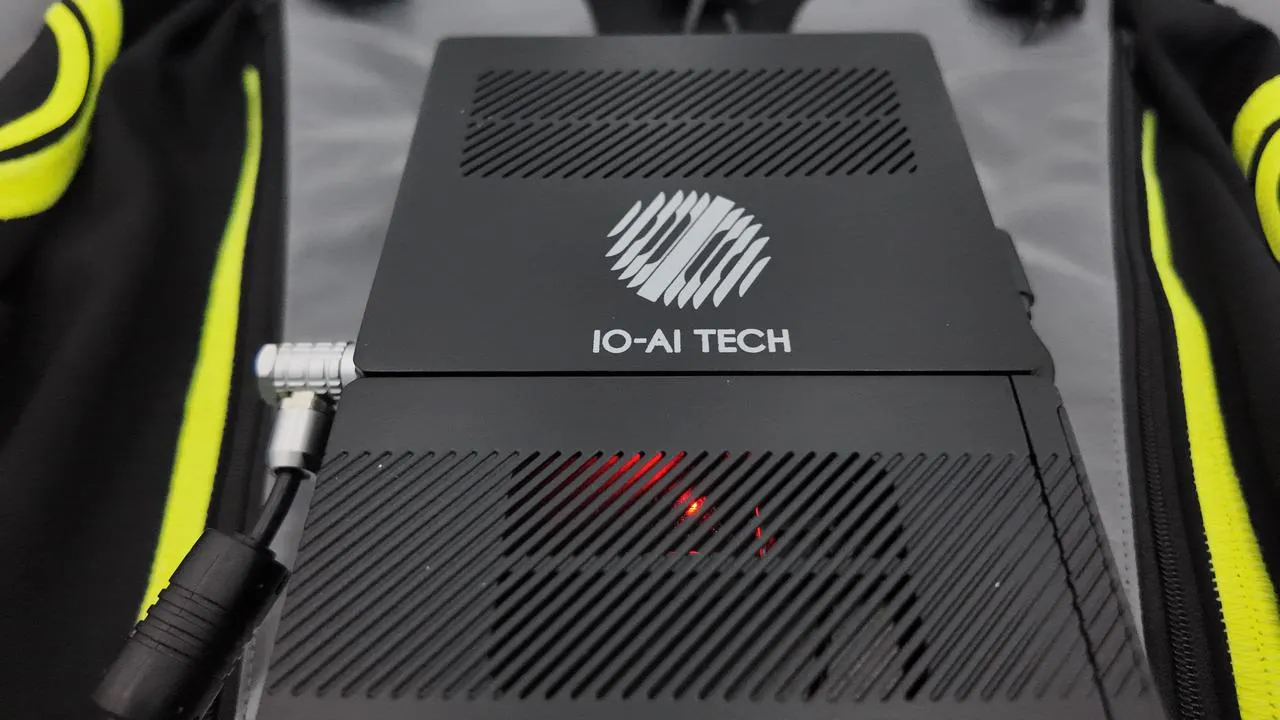
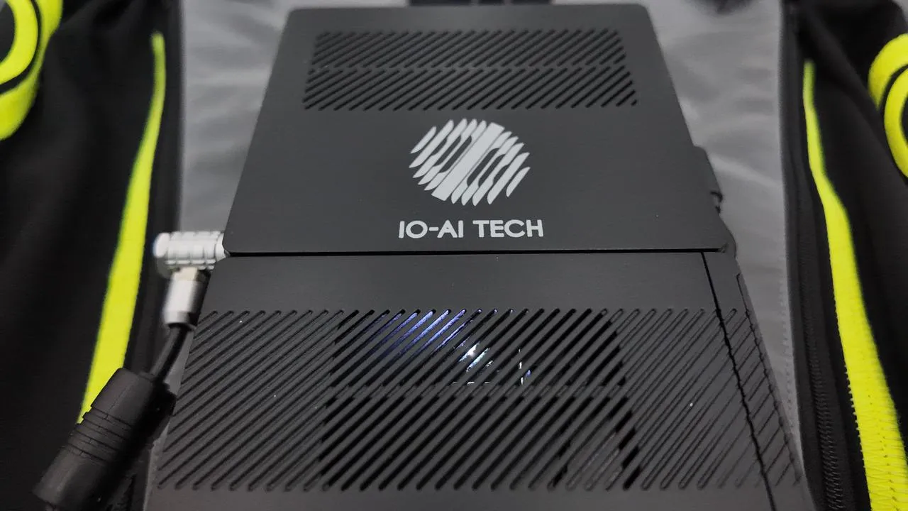
Router Indicator
- Solid Red: Indicates the router has started and is running normally.
- Solid White: Indicates wireless relay function is enabled and has successfully connected to external internet.
Connect VR to TeleSuit Main Control
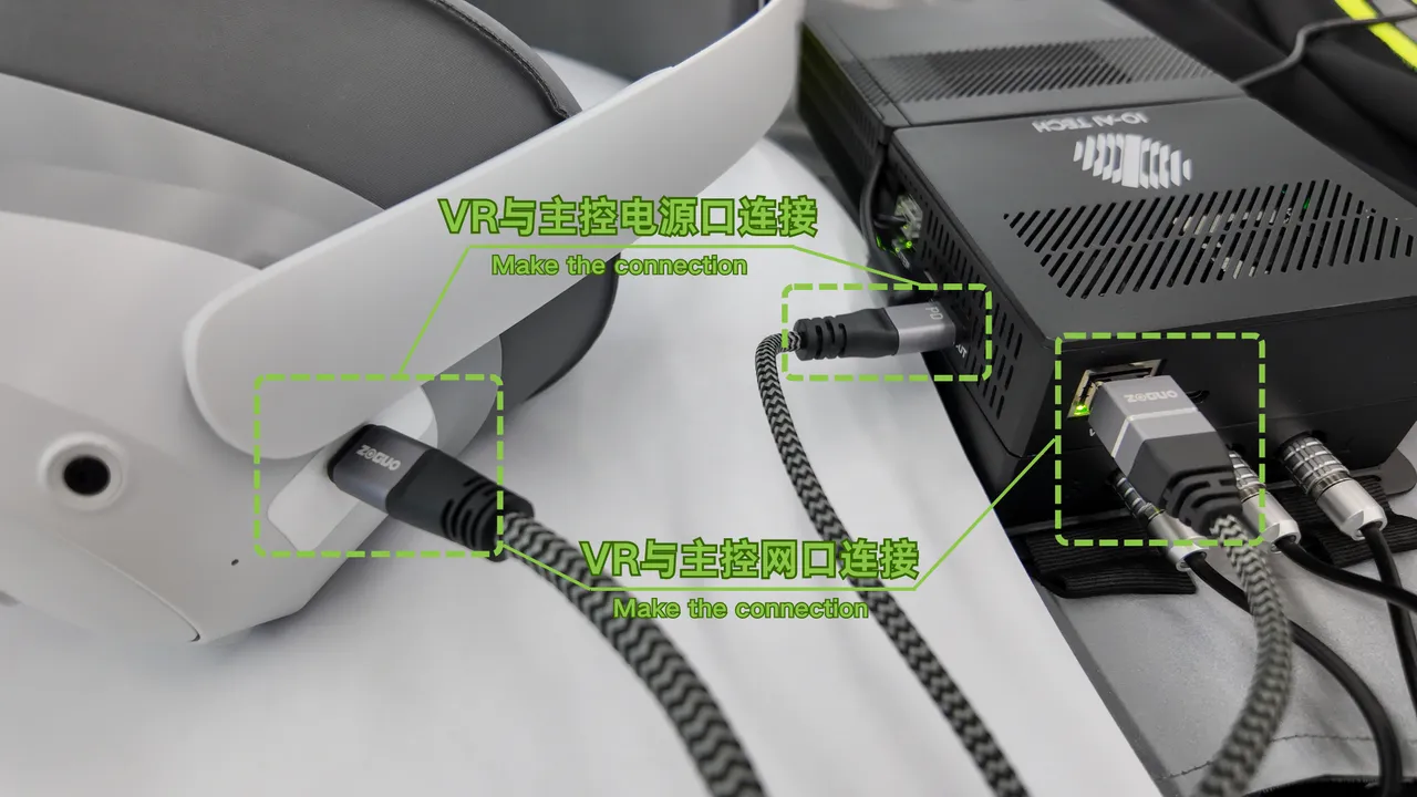
Wired Connection
Use the factory-supplied one-to-two connection cable: connect the network cable to the main control's network port and the Type-C cable to the main control's power port.
Wireless Connection
Refer to the Wi-Fi Connection section to connect the VR to the TeleSuit main control Wi-Fi.
TeleSuit main control Wi-Fi names are typically formatted as IO_5G_***** or IO_2.4G_*****, where ***** is the device serial number. The password is minnanoIO2023.
Connect Mocap Motion Capture Suit
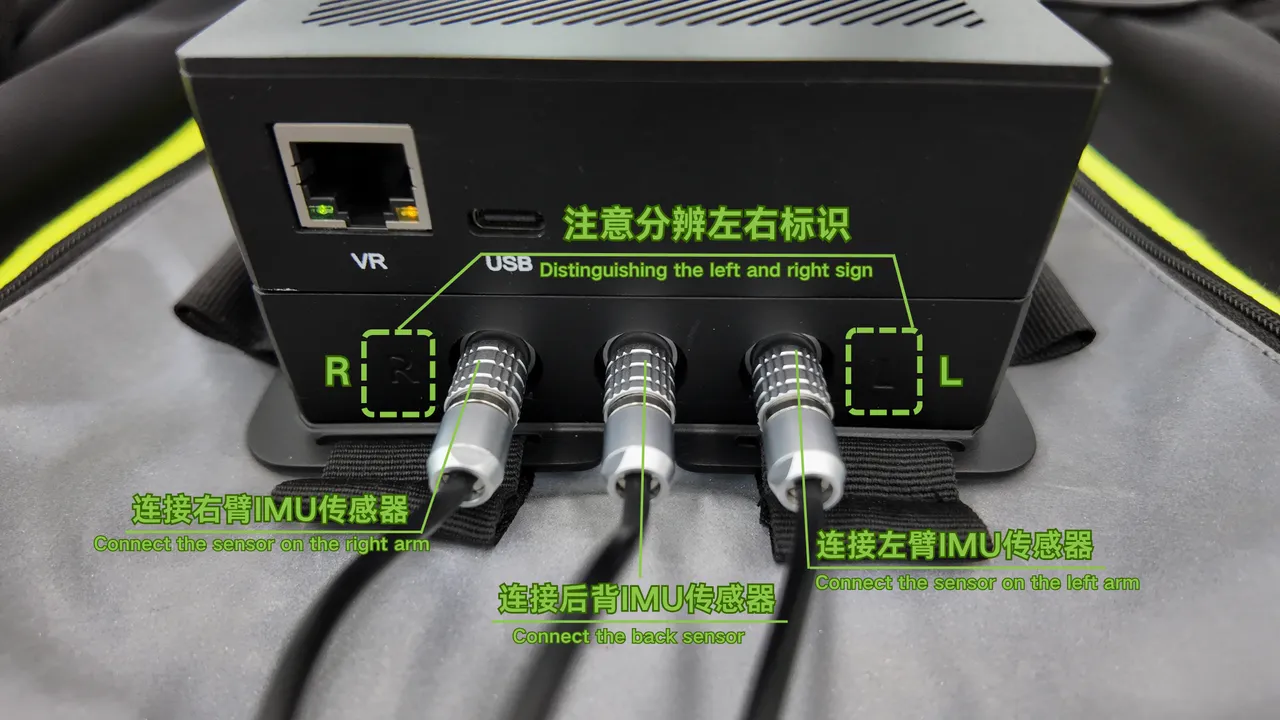
Upper Body
Usually connected by default at the factory. Before each use, check that the upper body aviation plugs are secure to ensure normal device operation.
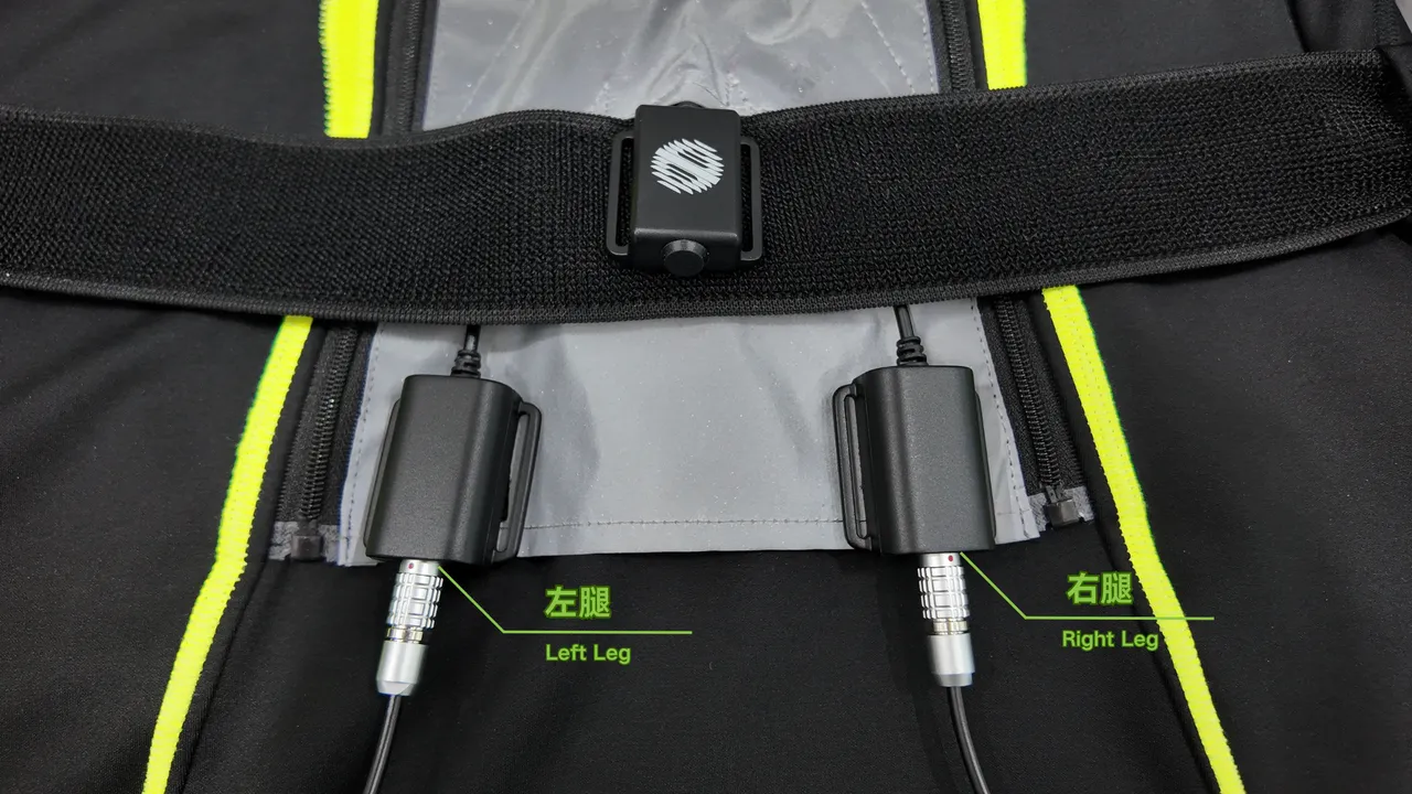
Lower Body
Two aviation plugs are located at the waist. When connecting, pay attention to the left and right order to ensure correct connection and avoid affecting device use.
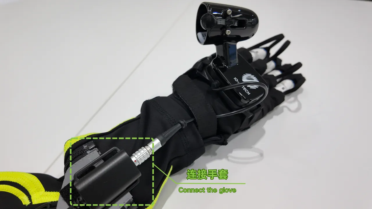
Motion Capture Gloves
Connect the left and right hand gloves separately, paying attention to distinguish left and right to ensure correct connection order.
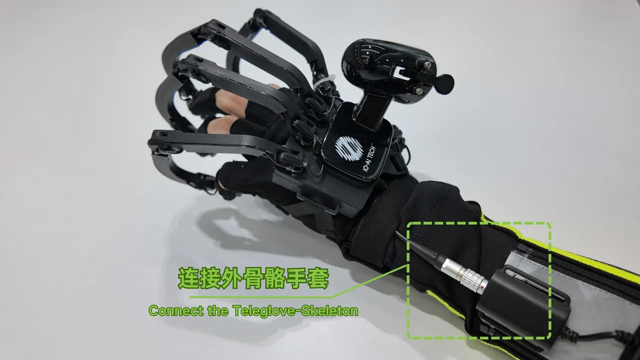
Wired Exoskeleton Gloves
Wireless Exoskeleton Gloves
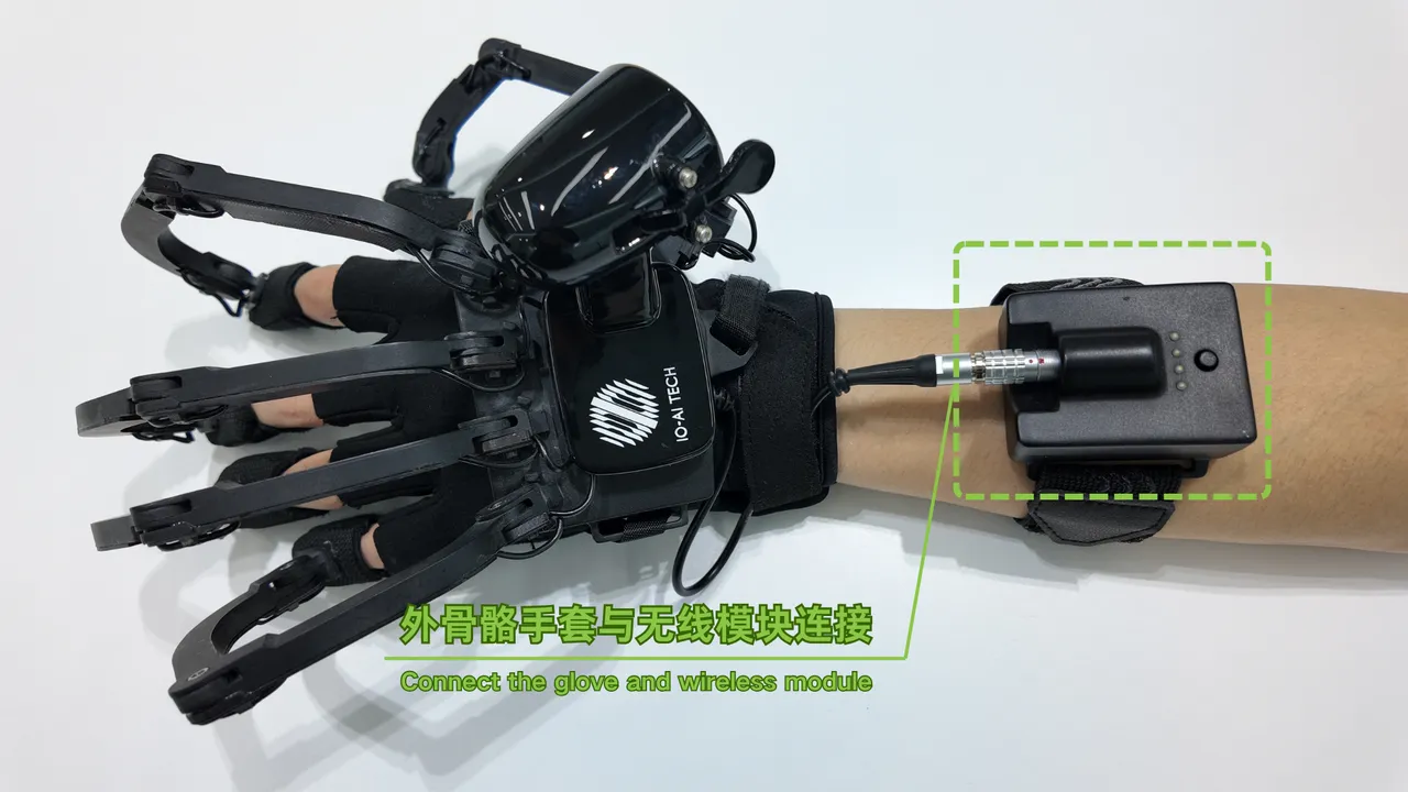
Click to expand wireless module usage instructions
Control Buttons
| Function | Operation |
|---|---|
| Power on | Short press → hold for 3 seconds (battery light flashes once) → release |
| Power off | Short press → hold for 3 seconds (battery light flashes once) → release |
| Check battery when powered off | Short press |
| Enter pairing mode | 1. While powered on: short press → hold for 3 seconds (battery light flashes once) → continue holding for 10 seconds (blue light on) → release → device powers off 2. Power on again: short press → hold for 3 seconds (battery light flashes once) → release → enter pairing mode (blue light on) |
Indicator Lights
| Status | Indicator |
|---|---|
| No Wi-Fi connection | Solid red |
| Listening mode / pairing mode | Solid blue |
| Wi-Fi connected, no data transmission | Solid green |
| Wi-Fi connected, data transmission active | Green blinking |
| Reading intrinsic parameters | Blue blinking |
| Device discovered | Blue-green blinking |
First-Time Pairing Steps
-
Connect power and turn on the TeleSuit 3.0 device.
-
Turn on the wireless module: use "short press + long press" on the device button to power on.
-
Switch the wireless module to pairing mode:
- Step 1: While powered on: short press → hold for 3 seconds (battery light flashes once) → continue holding for 10 seconds (blue light on) → release → device powers off;
- Step 2: Power on again: short press → hold for 3 seconds (battery light flashes once) → release → enter pairing mode (blue light on).
-
Configure Wi-Fi:
- Connect your PC to the TeleSuit Wi-Fi 2.4G band (e.g.,
IO_2.4G_*****) and open10.42.0.2:8686. - Click the WIRELESS_MODULE CONFIG button to enter the wireless module configuration interface.
- Connect your PC to the TeleSuit Wi-Fi 2.4G band (e.g.,

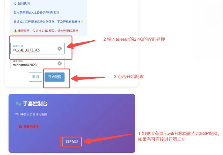
- Perform ESP network configuration:
- In the "Glove Console", click ESP Network Config.
- Enter the TeleSuit device Wi-Fi name.
- Enter the password (pre-filled by default).
- Click Start Configuration.
- Bind devices:
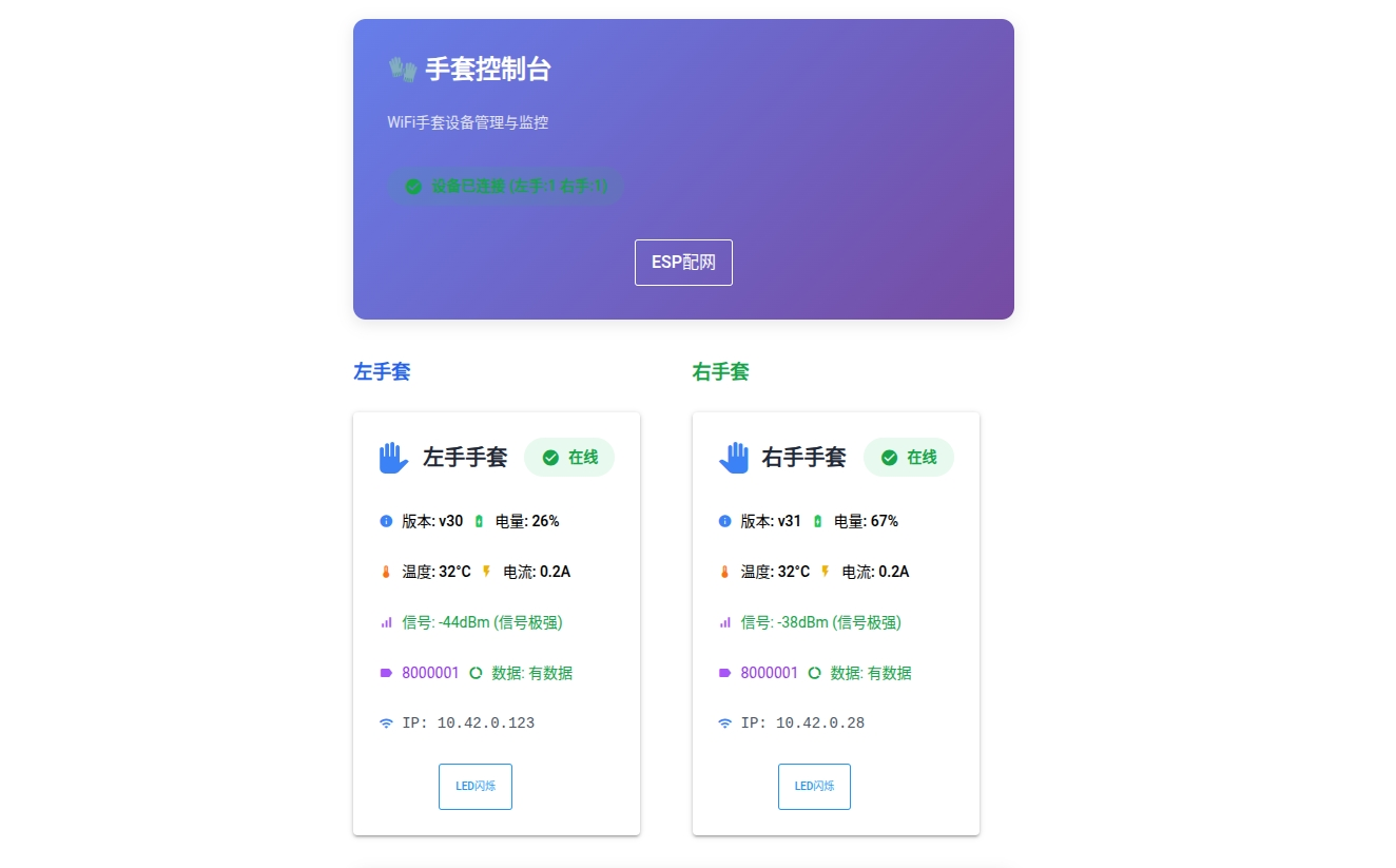
- Check the wireless module indicator — it should change from blue to green blinking.
- The system will automatically identify and bind left/right hand devices.
- Check the "Glove Console" interface to confirm successful binding.
- You can click LED Flash to identify the corresponding device.
Start Using After Pairing
- Put on the wireless modules and exoskeleton gloves in order, connect and power on the devices, and confirm the wireless module indicator is green blinking.
- You can now click START MOCAP to start the device.
TeleBox Connection Methods
Power Connection
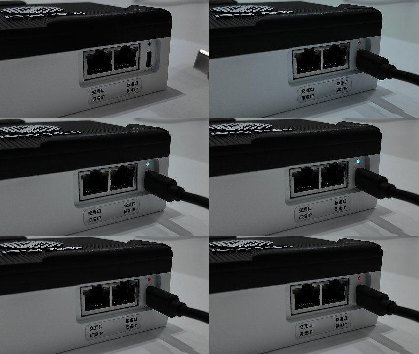
Insert the power supply into the Type-C port to power on the TeleBox.
System Indicator
After power-on, the indicator changes sequentially: red light indicates normal power-on; blue light indicates system initialization (about 5 seconds); red-blue alternating blinking indicates initialization complete and device ready.
Collection Mode (Factory Mode)
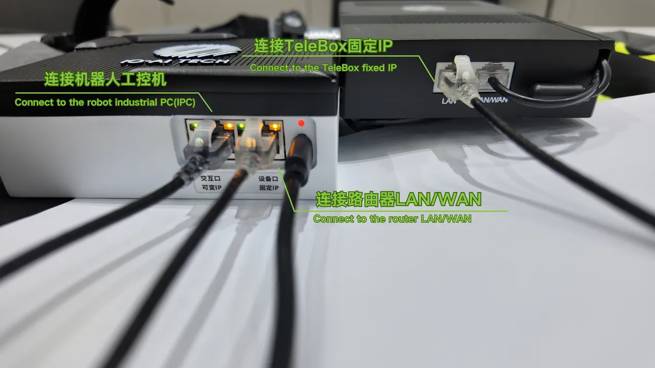
Connection Method
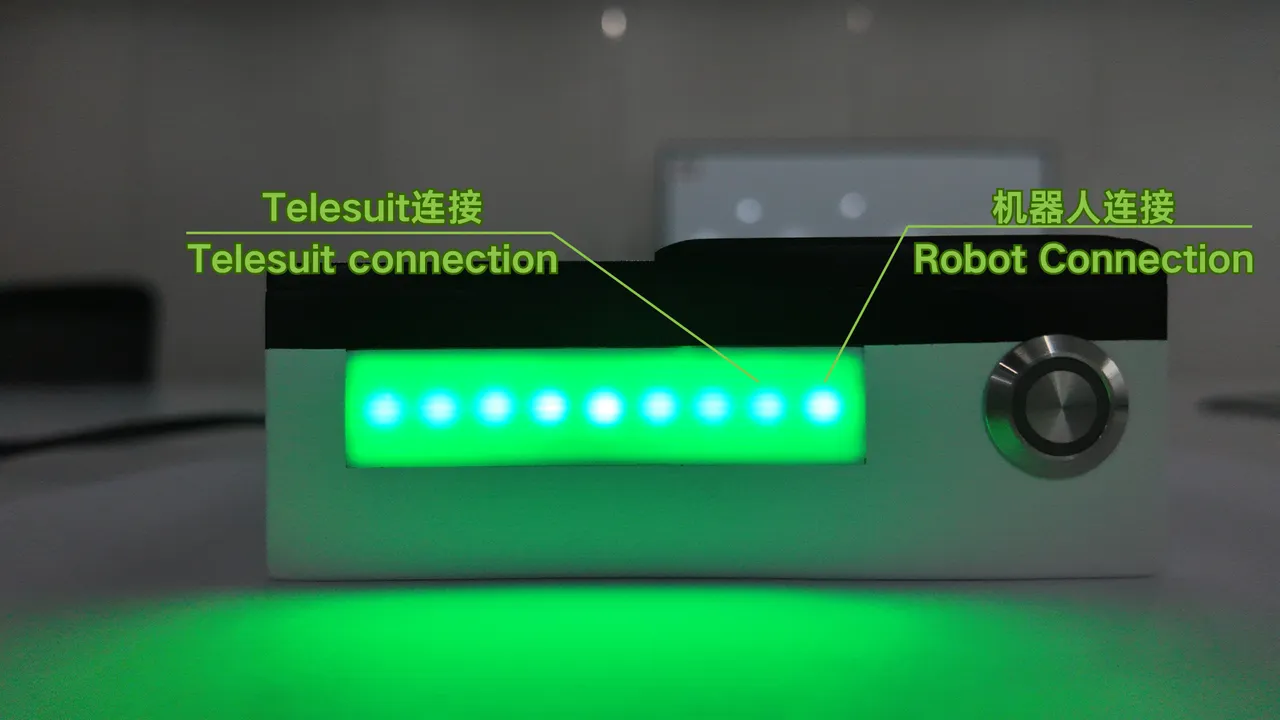
Status Panel Indicator
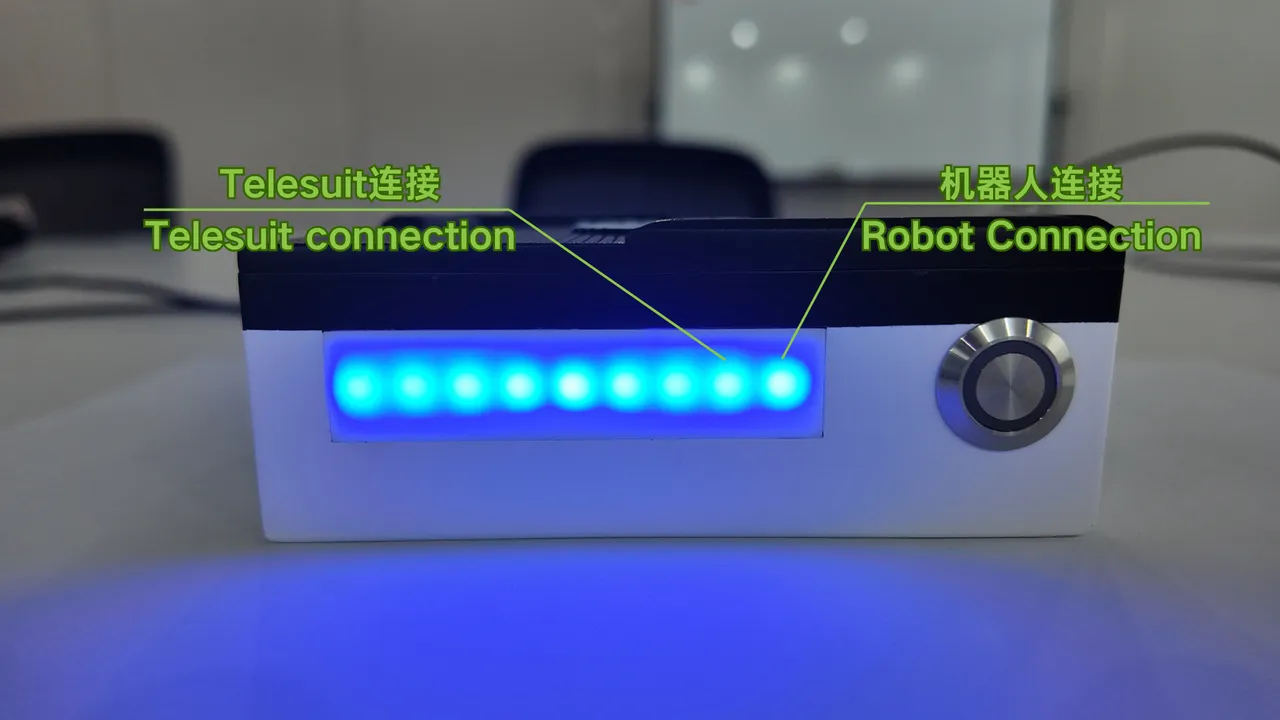
When all connections are normal, the indicators show all green; if TeleSuit cannot be connected, the second indicator from the right will turn red; if the robot cannot be connected, the first indicator from the right will turn red.
Upload Mode
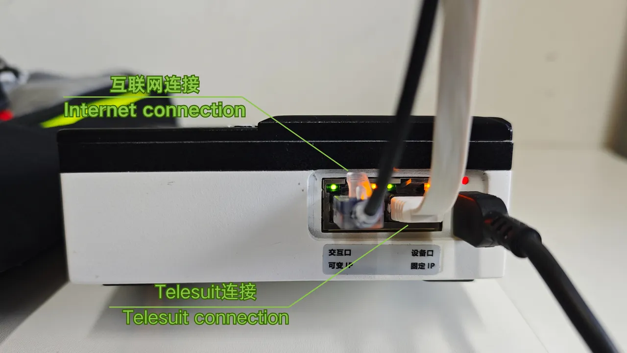
Connection Method
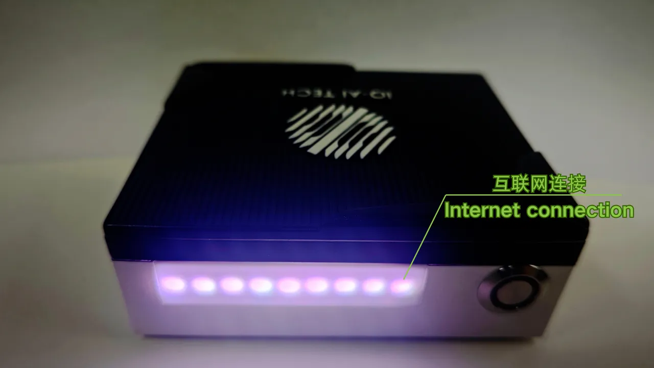
Status Panel Indicator
When all connections are normal, the indicators show all white; if internet cannot be connected, the first indicator from the right will turn red.
Remote Mode
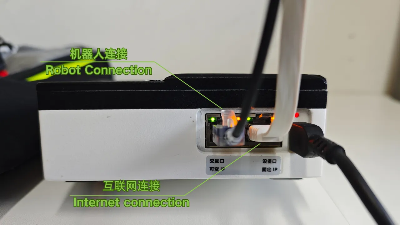
Connection Method
Status Panel Indicator
When all connections are normal, the indicators show all blue; if TeleSuit cannot be connected, the second indicator from the right will turn red; if the robot cannot be connected, the first indicator from the right will turn red.