VR App Usage Guide
PICO System Settings
Safety Boundary Setup
Go to System Settings > Safety Protection > Set Safety Boundary, click Go to Settings, then follow the video instructions.
Wi-Fi Connection
In the VR system, click the Wi-Fi icon in the bottom right corner, go to Network Settings, and connect to TeleSuit Wi-Fi.
TeleSuit main control Wi-Fi names are typically formatted as IO_5G_***** or IO_2.4G_*****, where ***** is the device serial number. The password is minnanoIO2023.


Wireless Screen Mirroring
Before screen mirroring, make sure the computer and VR headset are connected to the same Wi-Fi network. Otherwise, the mirroring device may not be found or connected.


Interface Overview
Startup Scene
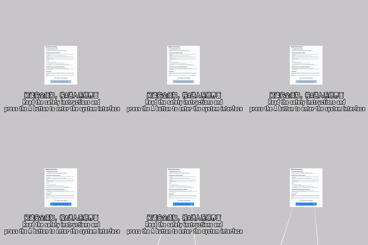
Startup animation and safety notice: After entering the scene, the system displays a safety notice with "Agreed" checked by default. After a 3-second countdown, press the A button on the right controller to agree and enter the main control scene. If you uncheck "Agreed", pressing A will exit the application.
Main Control Scene

Panel Introduction
Dock Navigation Bar

- Camera: Camera settings panel toggle
- MainControl: Main control center panel toggle
- Settings: System settings panel toggle
- Platform: Platform panel toggle
Camera, Settings, and Platform windows are mutually exclusive and share the same layer — they cannot be displayed simultaneously.
Main Control Center Panel
The main control center panel contains four sub-panels: TeleXperience, Dashboard, Frequency Monitor, and Battery Level.
TeleXperience Panel
Used for system control.

Error panel expansion: In normal state, click the ▽ icon to expand the panel and display system error information.
Unread error notification:
- When the MainControl panel is closed, if there are errors, the number of unread messages will be displayed in the top right corner of the MainControl icon in the Dock navigation bar.
- The unread count is automatically cleared after opening the status panel.
- Unread notifications are only effective when the MainControl panel is closed, excluding cases where the panel is hidden or minimized.
Mocap Settings Panel
Click the Mocap Settings icon to open/close the motion capture settings panel. For detailed functionality, see Motion Capture Features.

Trajectory Playback Panel
Click the Play Traj icon to open/close the trajectory playback panel. For detailed functionality, see Trajectory Playback.

Dashboard Panel
Displays teleoperation-related function status.

- Sync: Displays teleoperation synchronization status.
- Record: Displays teleoperation recording status.
- Count: Displays the number of recorded data entries in the system.
- Duration: Displays the recorded duration of current recording data.
Comm.Frequency Panel
Monitors network connection status with TeleSuit and TeleBox, and the output frequency of some messages.

- TeleSuit: Displays connection status with TeleSuit.
- TeleBox: Displays connection status with TeleBox.
- Joint State: Displays output frequency of
/io_teleop/joint_statesfrom the industrial PC subscribed by TeleBox. - Video: Displays communication frequency of camera data received by VR App. Click video_0 to switch to displaying multiple camera communication frequencies simultaneously.
- Target Pose: Displays output frequency of
/io_teleop/target_ee_posesfrom TeleSuit subscribed by TeleBox. - Hand Gesture: Displays output frequency of
/io_fusion/tffrom TeleSuit subscribed by TeleBox (when IMU gloves are connected) or/io_fusion/tf_exoskeletonfrom TeleSuit subscribed by TeleBox (when exoskeleton gloves are connected). - VR Data: Displays communication frequency of VrData sent from VR App to TeleSuit.
Before starting teleoperation, make sure the TeleSuit and TeleBox connection statuses are normal (no red icons) and the communication frequencies for Joint State and VR Data are both non-zero. If a connection status is abnormal or either frequency is 0, the related communication may not have been established. Check the connections between the VR headset, robot/industrial PC, and TeleSuit, and start teleoperation only after confirming communication is normal. For connection setup, see Communication Connection.
Network Disconnection Alert
- During system operation, the system automatically monitors communication connection status with TeleSuit (
10.42.0.2). - If the network connection with TeleSuit is interrupted, the system will pop up a network connection failure panel. This panel will remain displayed until the network is restored.

Battery Level Panel
Displays battery information for all system modules.


- VR Headset: Displays headset battery level.
- L-Con: Displays left controller connection status and remaining battery.
- R-Con: Displays right controller connection status and remaining battery.
- TeleSuit: Displays TeleSuit battery level or DC power supply status.
Robot Panel
The robot panel automatically displays when the system communicates normally with TeleBox.

- The robot model is completely missing: If TeleBox communication is normal but the model is still not visible, the robot may not have a corresponding VR visualization model yet. Contact your sales representative to ask about custom development.
- The model is incomplete or appears as a white model: Check the mesh files referenced by the URDF. If their total size is too large, the browser may not render the model correctly. Keep the total size of all mesh files below 50 MB. See Adaptation Requirements for details.
Mocap Avatar Panel
The mocap avatar panel automatically displays when Mocap is successfully enabled.

Camera Panel
For detailed camera functionality, see Camera Features.

Platform Panel

System Version Display
Enabled by default.
Automatically displays the following information in the upper right corner of the scene:
- VR version
- Suit version
- Box version
Interaction Methods
Panel Show/Hide
Click an icon to show a panel, click the same icon again to hide it.

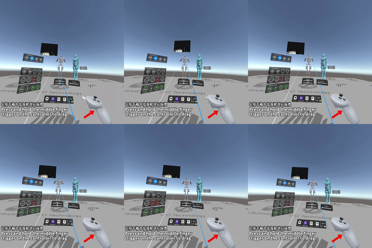
Panel Dragging
Select the panel's valid area with the middle finger trigger, then drag.
- Applicable Areas

- Action Demo
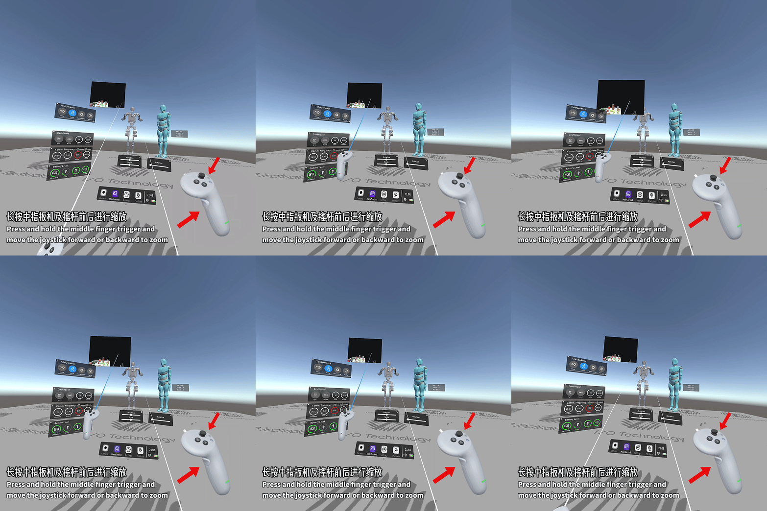
Panel Distance Adjustment
Select the panel's valid area with the middle finger trigger, then push/pull the joystick forward/backward to control panel distance.
- Applicable Areas

- Action Demo
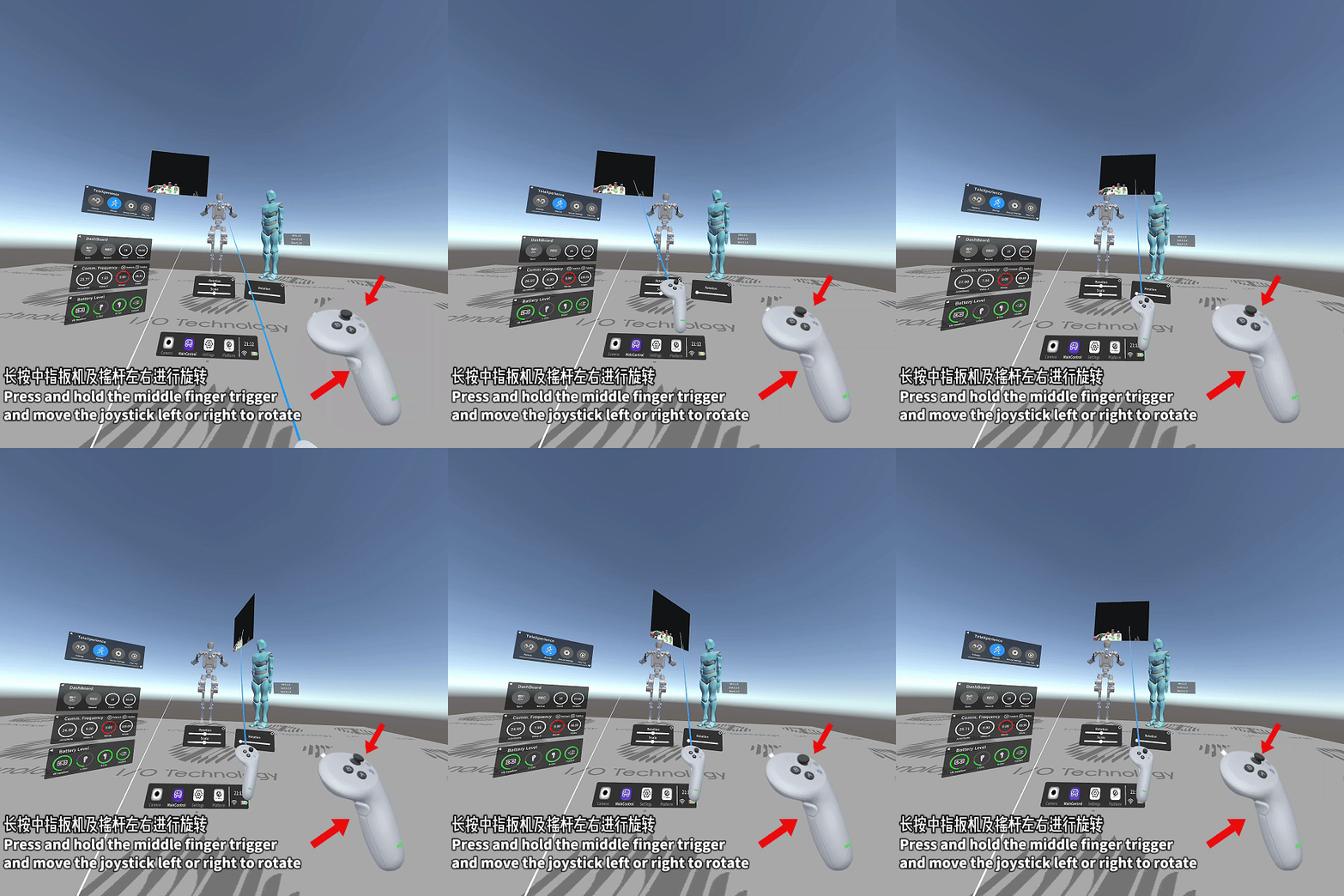
Panel Orientation Adjustment
Select the panel's valid area with the middle finger trigger, then push the joystick left/right to control panel orientation.
- Applicable Areas

- Action Demo
Panel Scaling
When moving the ray to the four corners of a panel window, white sphere anchor points appear. Hold the middle finger trigger and drag the anchor points to scale.
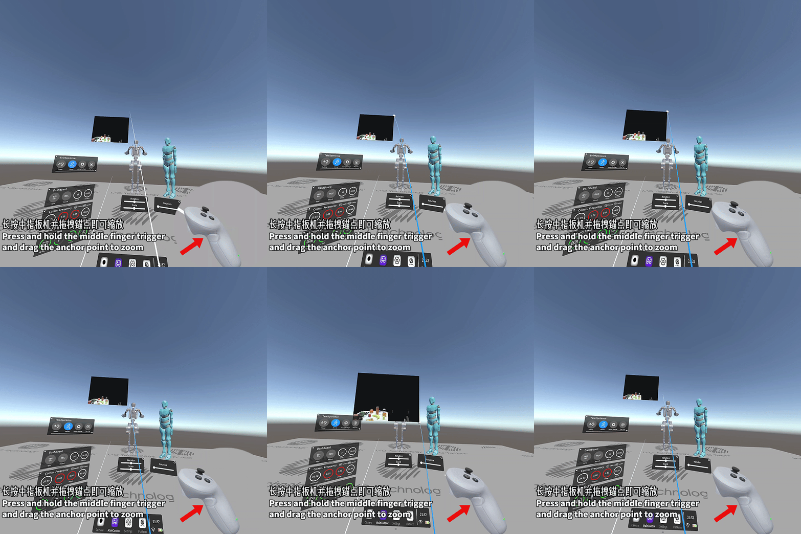
Currently only the camera panel supports this operation.
Panel Reset
Long press the corresponding icon to reset the current panel position/size to default.
-
Dock navigation bar reset: Long press the controller Home button to restore the Dock navigation bar to its initial position.
-
Camera panel reset: Long press the Camera icon.

- Main system panel reset: Long press the MainControl icon.

- Robot panel reset: Long press the 🔄 icon in the robot panel.

- Mocap avatar panel reset: Long press the 🔄 icon in the mocap avatar panel.

Main Control Center Sub-panel Status Toggle
- Normal state: Normal display state with sub-panel content shown normally.
- Closed state: After clicking the MainControl icon, the sub-panel closes and no longer displays.
- Hand-following state: Sub-panel is only visible when raising your hand, appearing or disappearing with hand movements.
- Hidden state (in hand-following mode): In hand-following state, after clicking the Menu button, the sub-panel is hidden and no longer displays.
Sub-panel status toggle: Click the ◁ button to switch between normal state and hand-following state.
Hand Menu
Trigger method:
- Raise your left hand so the finger trigger in your field of view faces your face. A blue button appears in the bottom left corner as the hand menu toggle.
- If entering the app for the first time, it defaults to hidden state (in hand-following mode). First click the Menu button to enter hand-following state.
- Keep the controller at a 30° to 45° angle with your line of sight, and the panel in hand state will appear.


Component Layout Features
- In the system settings panel, click Layout, then click Add New to save the current panel position as a layout. Up to 5 layouts can be saved.
- Select a saved layout template from the dropdown list. Click Delete to remove the current template, or click Apply to apply the selected layout.
- Click the Reset button to restore all component layouts to default with one click.
If the number of cameras in the current template does not match the actual number of cameras, the layout application will not be executed. Users need to select a template with a matching number.
Passthrough Mode
- When enabled, the system stops rendering virtual content and only displays real-world camera footage.
- Quick start/exit: Press both joystick buttons simultaneously to start passthrough mode, press again to exit.

Immersive Mode
When enabled, the camera panel automatically follows head movements. You can set whether to display the robot and mocap avatar in immersive mode.

Motion Capture Features
View Motion Capture Device List
Click the Mocap Settings button to open the motion capture settings panel, then click the Device List button on the left. The right list will display currently connected available devices.
Motion Capture Calibration
This feature is only available when motion capture is enabled.
In the motion capture settings panel, you can perform the following calibration operations:
- Click the Pose Calib button to choose Pose Calibration or Quick Pose Calibration.
- Click the VR Calib button to choose VR Motion Capture Joint Calibration - VRHead or VR Motion Capture Joint Calibration - VRController.
- Click the Params Calib button to choose Online Magnetic Field Calibration.
Motion capture calibration guide animation is enabled by default. After checking Guided Animation, the system will play corresponding animations at each calibration stage as guidance. Refer to the tutorial videos for specific movement details.
Pose Calibration
Refer to the following video to learn the calibration process and key movements.
Click the BODYCalib button, and the system will automatically start the calibration process based on the selected combination.
Quick Pose Calibration
For scenarios requiring fast pose calibration. Faster than existing pose calibration but with slightly reduced accuracy — choose based on your actual needs.
Follow the calibration guidance and voice prompts displayed on the interface.
VR Motion Capture Joint Calibration - VRHead
Refer to the following video to learn the calibration process and key movements.
Click the CalibVRHeader button, and the system will automatically start the calibration process.
VR Motion Capture Joint Calibration - VRController
Refer to the following video to learn the calibration process and key movements.
Click the CalibVRController button, and the system will automatically start the calibration process.
Online Magnetic Field Calibration
For quick magnetometer calibration while wearing the motion capture suit. Follow the calibration guidance and voice prompts displayed on the interface.
Exoskeleton Glove Visualization
When exoskeleton gloves are enabled and motion capture is active, double-click the upper body of the mocap avatar with the controller index finger trigger to toggle exoskeleton glove visualization.
When exoskeleton glove visualization is enabled, closing motion capture will also close visualization. To use it again, double-click the mocap avatar's upper body to enable exoskeleton glove visualization.


End-Effector Position Mapping Scale Adjustment
Disabled by default. This feature allows adjusting the robot's linear velocity when following the operator's hand movements by adjusting the end-effector position mapping scale factor. The system currently provides one mode: Custom, which can be enabled in the system settings panel.
- Custom Mode: The scale factor is a user-defined fixed value. After entering the desired coefficient, click the Apply button to apply.
- Before starting teleoperation, set the scale factor in advance:
- When coefficient > 1, robot movement speed is greater than hand movement.
- When coefficient < 1, robot movement speed is less than hand movement.

Camera Features
Based on the camera configuration in TeleBox's Dashboard, the camera settings panel displays the corresponding number of camera windows. Each window has a checkbox at the bottom. Check it to display the corresponding camera panel.
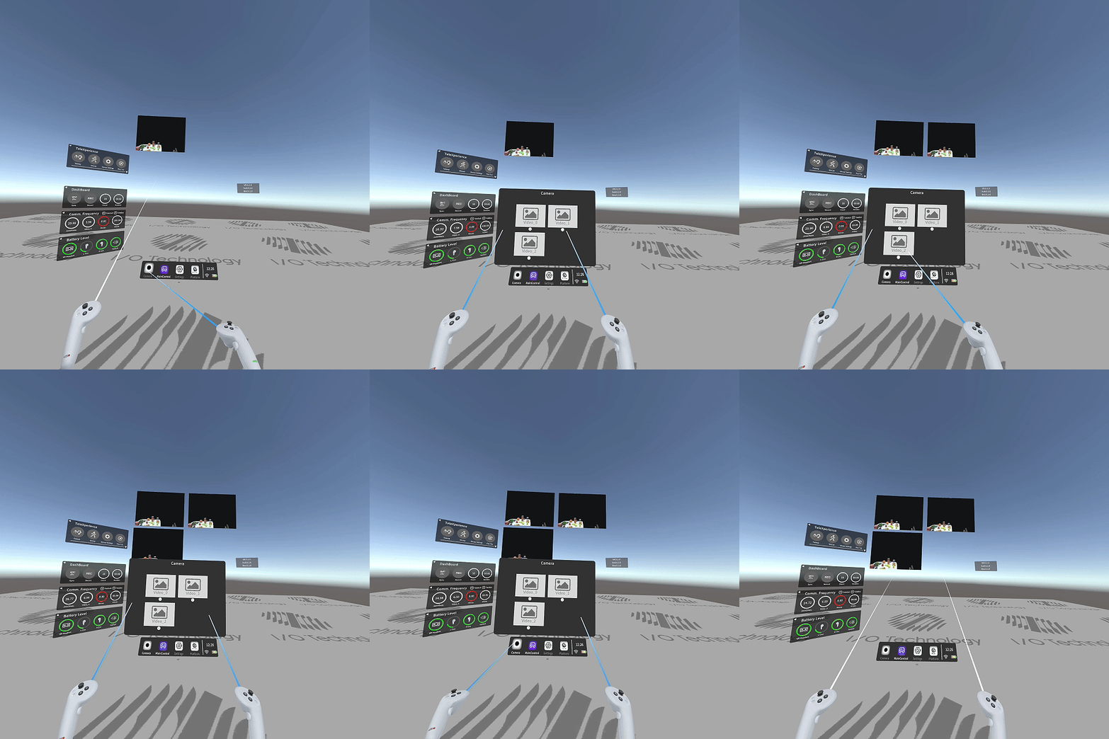
If you configured a stereo camera, you can double-click the camera icon in the taskbar to open the stereo camera view. Double-click again to close.
You can also enable or disable stereo camera mode in settings.
Trajectory Playback
Click the Play Traj button to open the playback panel. Click again to close it. The panel is shown below:
- Select data package: The system defaults to selecting the latest data package. You can also choose from the dropdown menu.
- Start playback: Click Start to begin playback.
- Stop playback: During playback, the Start button becomes Stop. Click it to stop playback. If you click the Play Traj button to exit the panel directly, the system will prompt you to confirm stopping playback before exiting.
- Status display and sync: Typically, VR App automatically syncs trajectory playback status and displays a green indicator and sync success message below the panel — no manual sync needed. If a red indicator and sync failure message appear, click the 🔄 button to manually sync status.
Safety Features
Controller Abnormal Pose Filtering
Enabled by default.
To improve system safety, this feature filters out abnormal large jumps in VR controller pose recognition results. Users can choose whether to enable this feature based on the robot's actual motion performance and set filtering threshold parameters to adapt to different scenarios. After entering the desired threshold parameters, click the Apply button to apply.

Controller Vibration Feedback
When vibration data is received, the controller will vibrate. The incoming data mainly controls vibration amplitude, with the following parameters:
- Vibration amplitude: Received data value multiplied by 0.8 as the actual vibration amplitude.
- Vibration duration: 500 milliseconds.
- Vibration frequency: 100 Hz.
Fatigue Detection
When system runtime reaches a specified threshold (20 minutes, 40 minutes, or 60 minutes), the system automatically pops up a fatigue detection panel to remind users to check their status and rest appropriately.

Low Battery Detection
Enabled by default.
- During program operation, if VR or TeleSuit battery drops below 20%, the system triggers a low battery warning once.
- If either device's battery drops below 5%, the system automatically disables synchronization after starting sync.
- To disable this feature, uncheck the Low Power Warning option in the PoseCalib page of the system settings panel.

Other
Config Switch Monitoring
After detecting a reapply configuration (Config) operation, the system will perform the following steps:
- Re-pull the configuration file.
- Restart WebSocket communication.
- Reload robot model and camera panels.
Language Switch
The system currently supports Chinese and English. The default language is English. Users can switch languages in the Language page of the system settings panel.